iFLOW HVAC INC.
www.iflowhvac.com
14
1) Procedure:
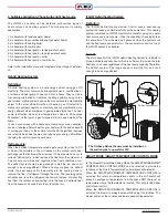
Do not start the boiler or water heater until ALL air has been purged
from the water lines and air handler pump.
1. Fill the boiler loop or water heater with water. Do not start it.
2. Purge all air from the heating boiler or domestic hot water system
(Hold the UP & ENTER button for 10 seconds and then the circulator
will alternate power ON and OFF for about 10 minutes to purge air).
3. Purge all air from the space heating loop by closing the isolation
valve on the return leg of the loop and open the drain to purge the air.
Open the return leg isolation valve and then close the drain valve.
4. If a bleed screw is not present, it is recommended to run the pump
on speed #3 for 1 minute. If air is still present, switch from speed #1
to #3 every 10 seconds for a minute.
5. Start the boiler or water heater according to the manufacturer’s
instructions. Set the design water temperature and wait for the
system to satisfy and shut off.
6. Turn on the power to the iFLOW air handler and set the room
thermostat to ‘heat’ to energize the fan and pump. If noise is still
present after one minute, repeat step #3 to purge air.
7. Check supply and return pipes for temperature differences to
make sure there is flow. There should be a noticeable difference in
temperature. Use caution when supply water temperature is above
120˚ F.
2) Flushing the heat exchanger:
Flushing the hot water coil prior to startup is required to remove any
residual material from the installation or manufacturing processes as
well as to remove any air from the system. Take precautions while
flushing the air handler to prevent the multi-function control board and
other electrical components from getting wet.
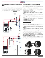
The iFLOW air handler requires an external circulating pump to be
installed and should be installed with an external purge valve.
Flushing is a 3-step process:
1) Use a bucket or hose to dispose of water during the flushing
process. First, flush the return line by closing the inlet valve (supply)
and opening the outlet valve (return). Open the purge valve. Close
the purge valve once flushing is complete.
2) Second, flush the supply line and coil by closing the outlet valve
(return) and opening the inlet valve (supply). Open the purge valve.
Close the purge valve once flushing is complete.
3) Third, apply power to the air handler. Open inlet and outlet valves.
Engage the pump and open the purge valve. Verify proper flow
direction - inlet valve should become warm before the outlet. Close
the purge valve once flushing is complete. Operate the pump for 5
minutes immediately after flushing the system to purge remaining air
from the pump bearing chamber.
3) Sequence of operation:
Cooling:
When the thermostat calls for cooling, the circuit between
R and G is completed. The normally open contacts close and the air
handler blower motor operates. The circuit between R and Y is also
completed; this closes the contact on the outdoor condenser unit.
The air handler fan turns off 45 seconds after the call for cooling is
completed.
Heating:
When the thermostat calls for heat, the circuit between R
and W is completed, activating the hot water circulating pump. A dry
switching relay labeled “T T” can be used to activate a boiler or combi
boiler. After the circuit between R and W is completed, a time delay
follows before the circuit between R and G is completed, which will
then activate the air handler blower motor.
Freeze protection:
If the temperature of the water in the hot water
coil drops below 40°F/4°C, the circuit between R and W is completed.
This will activate the circulating pump until the water temperature
reaches 70°F.
Pump timer/ exercise function:
The iFLOW control is equipped to
turn on the circulating pump to cycle the total volume of potable water
in the system if the pump has not been turned on within the past
24 hours. This function is skipped while the A/C condensing unit is
operating.
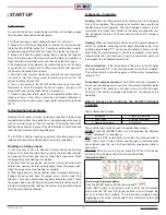
How to Access and Configure the iFLOW Intelligent
Controller
The controller has 6 modes:
The controller has 4 buttons used to navigate those modes:
MODE:
Press the ‘MODE’ button to scroll between the different
modes, numbered 1-6 (see above).
ENT:
Press the ‘ENT’ (enter) button to confirm the mode you wish to
enter. Press ‘enter’ to also confirm any changes or commands that
you selected using the ‘up’ and ‘down’ buttons (see below) while in
each mode.
UP & DN:
Once you are in a ‘mode’, press the ‘UP’ and ‘DN’ (down)
buttons to scroll all menu lists of the various information.
Information Mode
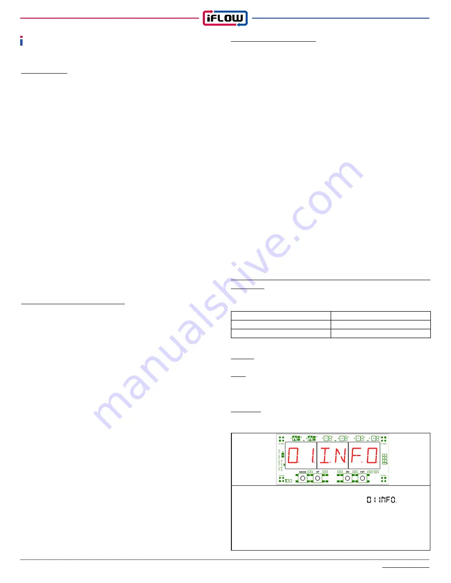
How to access Information display:
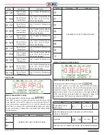
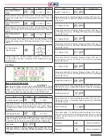
Push the ‘MODE’ button until the screen reads
Press ‘ENT’ (enter) to confirm you wish to enter the information
mode. Use the ‘UP’ and ‘DN’ (down) buttons to scroll through the
menu of information available. The information available varies
depending on the model of air handler. The 4 characters on the right
indicate the value.
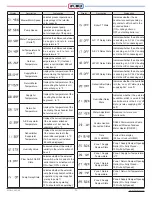
START-UP
1. Information
2. Error Codes
3. General Parameters
4. Heating Parameters
5. Cooling Parameters
6. Test Mode
Summary of Contents for iFLH-14000W
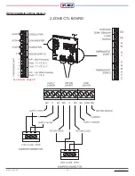
Page 24: ...iFLOW HVAC INC www iflowhvac com SZ Field Installation Wiring Diagram 24 See Details Page 29...
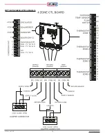
Page 26: ...iFLOW HVAC INC www iflowhvac com DZ Field Installation Wiring Diagram 26 See Details Page 29...
Page 28: ...iFLOW HVAC INC www iflowhvac com QZ Field Installation Wiring Diagram 28...
Page 30: ...iFLOW HVAC INC www iflowhvac com 4 Ladder Diagram 30...
Page 43: ...iFLOW HVAC INC www iflowhvac com 43 Installation on the wall...


