iFLOW HVAC INC.
www.iflowhvac.com
20
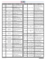
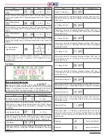
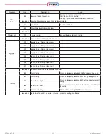
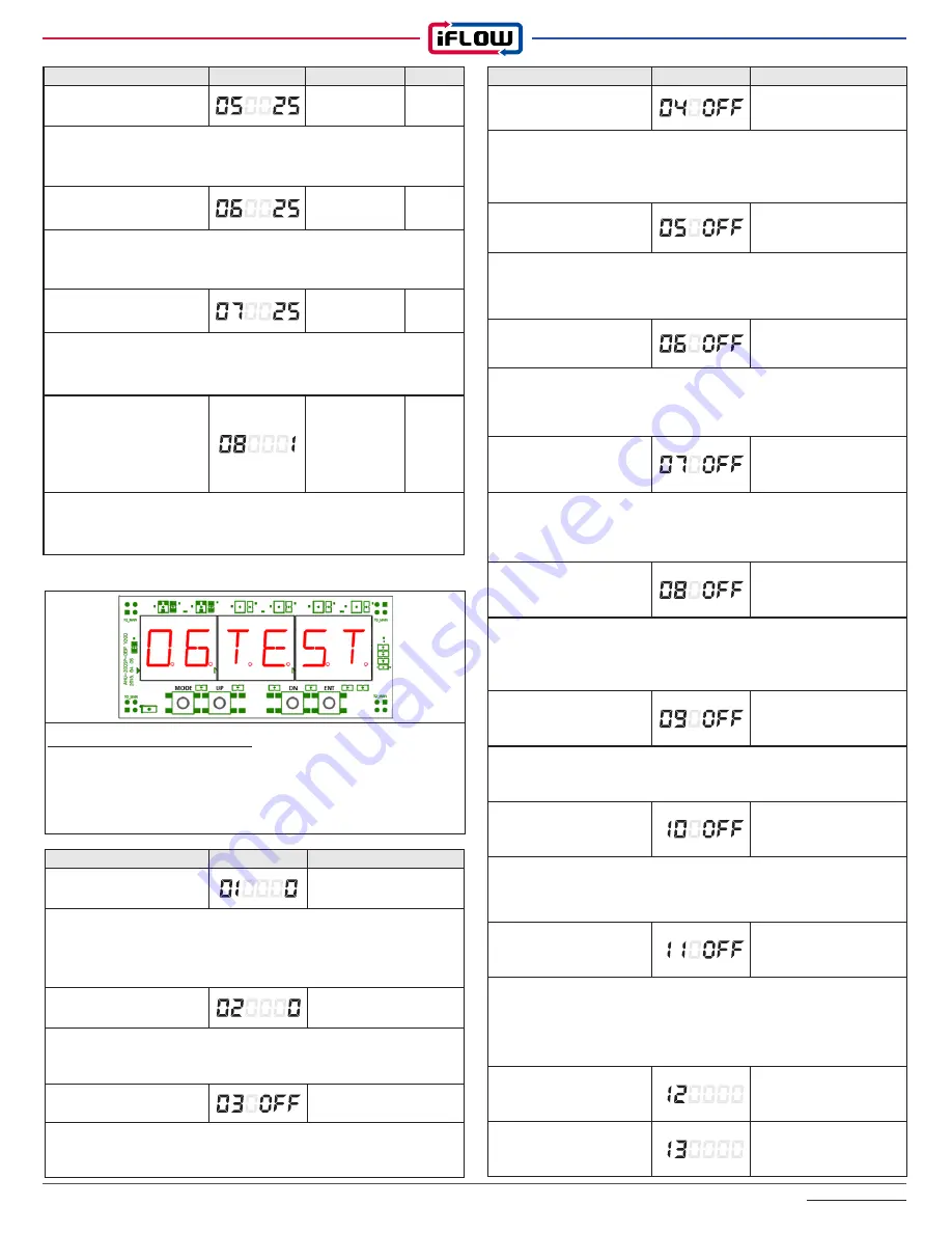
Test Mode
How to access Test codes:
Push the mode button until the screen reads
06TEST
. Press
‘ENT’ (enter) to confirm the test mode. Use the ‘UP’ and ‘DN’ (down)
buttons to scroll through the menu of tests, numbered 01-20. Use the
up and down buttons to change the values. Press ‘MODE’ to exit.
Item
Display
Test Operation
Boiler T T Relay Test
Press enter while 04 is flashing. Display will show OFF. Use ‘UP’ or
‘DN’ button to turn on. Boiler TT Relay will start immediately. Press
enter to exit.
H / P Relay W1 Test
Press enter while 05 is flashing. Display will show OFF. Use ‘UP’
or ‘DN’ button to turn on. H/P Relay W1 Test will start immediately.
Press enter to exit.
H / P Relay W2 Test
Press enter while 06 is flashing. Display will show OFF. Use ‘UP’
or ‘DN’ button to turn on. H/P Relay W2 Test will start immediately.
Press enter to exit.
A / C Relay Y1 Test
Press enter while 07 is flashing. Display will show OFF. Use ‘UP’
or ‘DN’ button to turn on. A/C Relay Y1 Test will start immediately.
Press enter to exit.
A / C Relay Y2 Test
Press enter while 08 is flashing. Display will show OFF. Use ‘UP’
or ‘DN’ button to turn on. A/C Relay Y2 Test will start immediately.
Press enter to exit.
Dehumidifier Relay Test
Press enter while 09 is flashing. Display will show OFF. Use ‘UP’ or
‘DN’ button to turn on. Dehumidifier Relay Test will start immediately.
Press enter to exit.
Humidity Relay Test
Press enter while 10 is flashing. Display will show OFF. Use ‘UP’ or
‘DN’ button to turn on. Humidifier Relay Test will start immediately.
Press enter to exit.
Flow Switch Test
Press enter while 11 is flashing. Jumper terminals FS on the right
side of the control board. The display will flash ON if it is working
correctly. You can also open a hot water faucet; this should trip the
switch to ON.
Reserved
Future cool function
Reserved
Future cool function
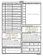
Item
Display
Test Operation
Blow Motor Speed Control
0 ~ 100%
Press enter while 01 is flashing. Display will flash 0. Use ‘UP’ or
‘DN’ buttons to change blower speed value from 0-100%. Blower
will speed up and down as you increase or decrease the value,
respectively.
Pump Speed Control
0 ~ 100 %
Press enter while 02 is flashing. Display will flash 0. Use ‘UP’ or ‘DN’
buttons to change value from 0-100% pump speed. Pump will speed
up and down as you increase or decrease the value, respectively.
Pump Relay
Press enter while 03 is flashing. Display will show OFF. Use ‘UP’ or
‘DN’ button to turn on. Relay test will start immediately. Press enter
to exit.
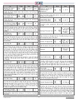
Item
Display
Range
Default
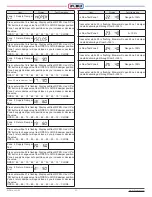
Zone 2 Blower Motor
Speed
0 ~ 100 %
25%
Set the blower motor speed for zone 2 as a percentage of the
home’s total cooling load or CFM requirement (see Zone 1 above for
details).
Zone 3 Blower Motor
Speed
0 ~ 100 %
25%
Set the blower motor speed for zone 3 as a percentage of the
home’s total cooling load or CFM requirement (see Zone 1 above for
details).
Zone 4 Blower Motor
Speed
0 ~ 100 %
25%
Set the blower motor speed for zone 4 as a percentage of the
home’s total cooling load or CFM requirement (see Zone 1 above for
details).
A/C Type Selection
(when Zoning)
0=single stage
A/C
1= inverter A/C
or HP
2=Inverter 2 A/
C or HP
1
0=Single stage A/C: all zone dampers will open. 1=inverter A/C:
1 zone will open at a time. 2=Inverter 2 A/C: multiple zones open
simultaneously
Summary of Contents for iFLH-14000W
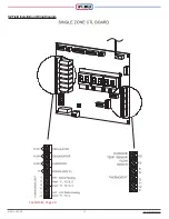
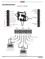
Page 24: ...iFLOW HVAC INC www iflowhvac com SZ Field Installation Wiring Diagram 24 See Details Page 29...
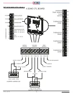
Page 26: ...iFLOW HVAC INC www iflowhvac com DZ Field Installation Wiring Diagram 26 See Details Page 29...
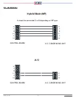
Page 28: ...iFLOW HVAC INC www iflowhvac com QZ Field Installation Wiring Diagram 28...
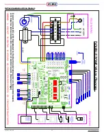
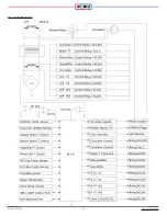
Page 30: ...iFLOW HVAC INC www iflowhvac com 4 Ladder Diagram 30...
Page 43: ...iFLOW HVAC INC www iflowhvac com 43 Installation on the wall...

