iFLOW HVAC INC.
www.iflowhvac.com
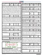
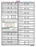
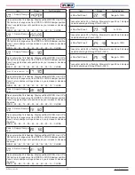
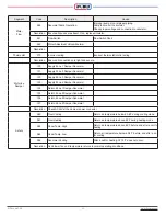
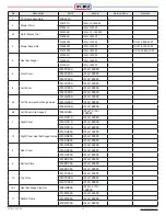
Segment
Code
Description
Cause
Water
Flow
060
Abnormal Pump Operation
Improper pump size. Improper piping.
Pump failure. Air in circulator.
Check proper voltage and connection to circulator.
Resolution Ensure all causes are absent. If so, replace circulator.
061
Flow Switch
Flow Switch Short
062
Water Adjustment Valve Abnormal
Resolution
Thermostat
070
Incorrect wiring
Incorrect thermostat/control wiring
Resolution Ensure all connections are tight and secure.
Motorize
Damper
120
Supply Zone 1 Damper Abnormal
121
Supply Zone 2 Damper Abnormal
122
Supply Zone 3 Damper Abnormal
123
Supply Zone 4 Damper Abnormal
124
Return Zone 1 Damper Abnormal
125
Return Zone 2 Damper Abnormal
126
Return Zone 3 Damper Abnormal
127
Return Zone 4 Damper Abnormal
Resolution Check AC24V at the damper power connector.
Safety
080
Over Cooling
Return air temperature below 60.8˚F during cooling mode
081
Over Heating
Return air temperature above 80˚F during heating mode
082
Room Temp. High
Return air temperature above 85˚F before and after a call for
heating
083
Room Temp. Low
Return air temperature below 60.8˚F before and after a call
for cooling
084
Abnormal Cooling
After a call for heating, ∆T 10˚F does not occur.
Resolution Run blower fan until temperature returns to normal operating conditions.
32
Summary of Contents for iFLH-14000W
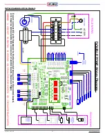
Page 24: ...iFLOW HVAC INC www iflowhvac com SZ Field Installation Wiring Diagram 24 See Details Page 29...
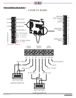
Page 26: ...iFLOW HVAC INC www iflowhvac com DZ Field Installation Wiring Diagram 26 See Details Page 29...
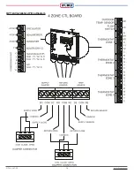
Page 28: ...iFLOW HVAC INC www iflowhvac com QZ Field Installation Wiring Diagram 28...
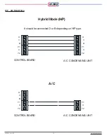
Page 30: ...iFLOW HVAC INC www iflowhvac com 4 Ladder Diagram 30...
Page 43: ...iFLOW HVAC INC www iflowhvac com 43 Installation on the wall...

