iFLOW HVAC INC.
www.iflowhvac.com
6
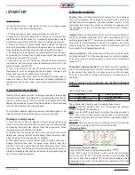
Set Back Recovery:
If a programmable thermostat with setback is used or a sudden
increase in temperature is required, the iFLOW intelligent control
board will modulate the air handler to its maximum output to speed
temperature delivery. The next cycle will return to normal operation.
See "Heat Boost Delay" Parameter.
Test Mode:
Entering ‘test mode’ on the controller will allow the technician to test
the iFLOW air handler heating and cooling mode parameters. Once
completed, push the test button again to return to normal operation.
Heating:
The iFLOW air handler will automatically change the fan and pump
speeds to control the temperature output of the unit and cycle-time
length. This will allow the heat output of the air handler to match the
current heat loss of the home. Maximum ‘matching’ performance is
achieved when used in conjunction with the outdoor sensor. This
leads to a longer runtime, providing superior warmth and comfort.
Cooling/Dehumidifying:
The iFLOW air handler uses a modulating blower fan to regulate
humidity levels. The blower fan speed decreases in high humidity
to remove moisture quicker. The blower fan speed increases under
normal conditions to provide optimal cooling. The balance of the two
is always met. Optimal humidity levels result in increased comfort
for the homeowner, and at the same time reduces cooling loads and
operating costs.
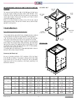
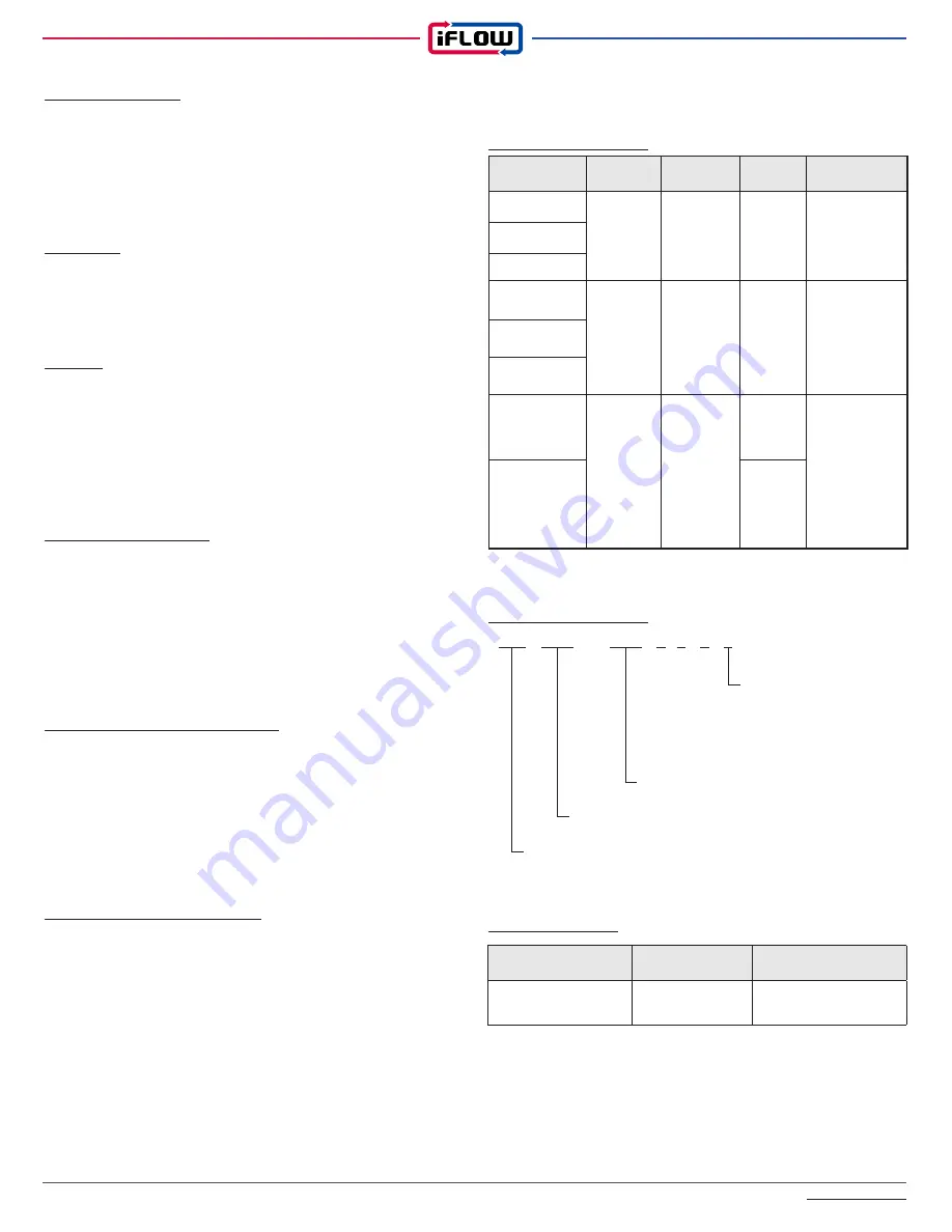
3. Equipment selection and sizing
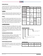
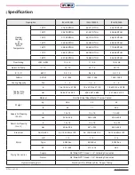
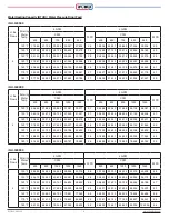
iFLOW air handlers are available in 3 models. Please use the
following charts to determine which best suits the application:
1. Obtain/calculate/determine a proper heat load for the home
2. Determine the inlet water temperature from water heater(or boilder)
3. Determine the duct layout/ available duct size
4. Be sure the system air flow rate matches the air flow rate of the
selected air handler
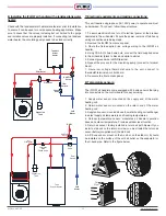
System Design Resource Note:
From the CAN/CSA-B214-12 Installation Code for Hydronic Heating
Systems, section 4.2.2.1 Heat-source output, it states: "the heat-
source output shall be not less than the heat load indicated in the
system design."
4.2.2.2 Dual-purpose water heater
Model No. Description
Model No.
Description WiFi @ IoT Zoning
Temperature
Control
iFLH-140000
iSmart
Control
No
No
Room
Thermostat
iFLH-160000
iFLH-180000
iFLH-14000W
iSmart
Control
WiFi
@
Internet/
Paring Mode
No
Room
Thermostat
or
Smart Mode
with
Smartphone
iFLH-16000W
iFLH-18000W
iFLH-16000D
iSmart
Control
WiFi
@
Internet/
Paring Mode
2 Supply
Zone
2 Return
Zone
Room
Thermostat
or
Smart Mode
with
Smartphone
iFLH-18000Q
4 Supply
Zone
4 Return
Zone
Model No. Description
Model No. Format
▶
i F L H - 1 4 0 0 0 0
Function / B: basic, W: WiFi,
D: 2 zone, Q: 4 zone
▶
▶
Cabinet Size / 14 : 14", 16 : 16", 18 : 18" Width
Static Pressure / L : Low Static Pressure,
H: High Static Pressure, LH : Universal
▶
Company Initial
Model No. Initial
Size
Function Initial
i F L H
14, 16, 18
B, W, D, Q, 0
Summary of Contents for iFLH-14000W
Page 24: ...iFLOW HVAC INC www iflowhvac com SZ Field Installation Wiring Diagram 24 See Details Page 29...
Page 26: ...iFLOW HVAC INC www iflowhvac com DZ Field Installation Wiring Diagram 26 See Details Page 29...
Page 28: ...iFLOW HVAC INC www iflowhvac com QZ Field Installation Wiring Diagram 28...
Page 30: ...iFLOW HVAC INC www iflowhvac com 4 Ladder Diagram 30...
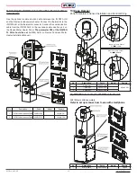
Page 43: ...iFLOW HVAC INC www iflowhvac com 43 Installation on the wall...


