mobileIoT gateway
CR3150
7
When bit 7 is written, the unit restarts.
4.3.1 Real-time mode
In real-time mode, bidirectional transmission of CAN messages occurs.
The unit can send/receive process data (e.g. machine parameters) via CAN interfaces during
operation via Bluetooth/WLAN, the mobile network and the
mobile
IoT platform. Depending on the
design, it can transmit data from the GNSS receiver and the input/output functions and forward them
via the CAN bus. Alternatively, the unit can receive the data from an external receiver (e.g.
CANwireless) via a WLAN or Bluetooth connection and send it to the
mobile
IoT platform.
The data is continuously transmitted and can be evaluated in near real-time. For this function, there
must be a permanent connection between the unit and the user software or the
mobile
IoT platform.
This mode also supports a real-time connection from Codesys 2.3. This requires appropriate software
and a
mobile
IoT data contract.
The real-time mode can be set locally via an SDO or via the
mobile
IoT suite in the machine properties.
In real-time mode, no data or messages are stored on the
mobile
IoT platform.
4.3.2 Cloud logging mode
In cloud logging mode, selected CAN messages are sent to the cloud, processed and stored. In this
case, the unit operates autonomously and does not have to be actively controlled by an application.
The configurations for this mode are made in the
mobile
IoT suite, which can send the data in CAN
messages. An OTA (over-the-air) configuration of the units is carried out via the
mobile
IoT suite.
4.3.3 IoT mode
The IoT mode is a combination of real-time mode and cloud logging mode. It makes it possible to
establish a real-time connection with the CAN bus and automatically send GNSS position data to the
mobile
IoT platform. In this mode, metrics are actively generated and sent by the application controller.
Data linking to the application controller is configured in the
mobile
IoT suite. There the corresponding
source code will be automatically generated, which can be loaded into the controller programme.
No data is sent to the
mobile
IoT platform during real-time connection. As soon as the real-time
connection is terminated, data is captured again and sent to the mobileIoT platform.
4.4 Input/output functions
The unit has additional input/output functions (3 analogue inputs, 1 digital output). For example, the
input function can be used to collect device or machine status information or to directly detect and
monitor switch states. The data determined via the input/output functions can be visualised or
transferred via the CAN bus.
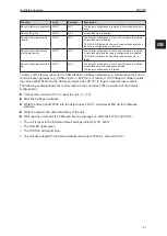
The input/output functions are accessed via the following objects:
Object
Index
Subindex
Type
Default
Description
Analogue input 1
0x546F
0x14
R32
ro
—
Pin 4 of the 14-pin Micro Timer II connector
Raw value of the analogue input measure-
ment (Volt)
No filtering applied
Analogue input 2
0x546F
0x15
R32
ro
—
Pin 5 of the 14-pin Micro Timer II connector
Raw value of the analogue input measure-
ment (Volt)
No filtering applied
GB


