background image

Seite / Page 10

1. Safety instructions

Observe the information of the description. Non-observance of the notes, operation which is not in
accordance with use as prescribed below, wrong installation or handling can result in serious harm
concerning the safety of persons and plant.

The instructions are for authorised persons according to the EMC and low voltage guidelines. The
controllers must be installed and commissioned by a skilled electrician (programmer or service
technician).

This description is part of the unit. It contains texts and drawings concerning the correct handling of the
controller and must be read before installation or use.

Since the unit has to be supplied with an external DC voltage (12/24 V) it must be ensured that the
external voltage is generated and supplied according to the criteria for safety extra-low voltage (SELV) as
this is supplied without further measures to the connected controller, the sensors, and the actuators.

The wiring of all signals in connection with the SELV circuit of the unit must also comply with the SELV
criteria (safe extra-low voltage, safe electrical separation from other electric circuits).

If the supplied SELV voltage has an external connection to ground (SELV becomes PELV) the
responsibility lies with the user and the respective national regulations for installation must be complied
with. All statements in these operating instructions refer to the unit the SELV voltage of which is not
grounded.

The terminals may only be supplied with the signals indicated in the technical data or on the unit label.
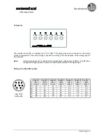
Only potential-free contacts or potentiometers can be connected to the Mini DIN sockets of the simulator.

The unit can be operated within a wide temperature range according to the technical specification
indicated below. Due to the additional self-heating the housing walls can have high perceptible
temperatures when touched in hot environments.

In case of malfunctions or uncertainties please contact the manufacturer.

2.  Function and features

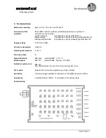
The simulator for the ecomat 100 control system type R 360 has been designed for testing application
software.

The unit has been designed in a way that it can be used for all input and output configurations of the
ecomat R 360 control system.

Important:

When used for other controllers the diagnostic box or the other controller can be destroyed.

Steuerungssysteme

Summary of Contents for ecomat 100 R 360

Page 1: ...Bedienungsanleitung Simulator Operating instructions Simulator ecomat 100 Typ R 360 articel no EC2014 Steuerungssysteme...

Page 2: ...rigen behalten wir uns technische nderungen der Produkte vor so da sich auch soweit Abweichungen vom Inhalt des Handbuches ergeben k nnen Technical description simulator March 1999 Note on guarantee U...

Page 3: ...en entsprechen sichere Schutzkleinspannung galvanisch sicher getrennt von anderen Stromkreisen Wird die extern zugef hrte SELV Spannung extern geerdet SELV wird zu PELV so geschieht dies in der Verant...

Page 4: ...K MC1 5 5 Anschu spannung 10 30 V DC VBB Stromaufnahme 400 mA Umgebungstemperatur 0 50 C Schutzklasse III Signalanzeige LED gr n Potential GND 0 7 V Ein Ausg nge LED rot Potential VBB ca 0 75 VBB Anze...

Page 5: ...omechanischen Gr nden fassen die ersten 5 Buchsen jeweils 6 Eing nge aus einer 8er Gruppe Eingangs Byte zusammen Die 6 Buche bedient die Eing nge 06 07 14 15 22 und 23 die Buchse 7 die Eing nge 30 31...

Page 6: ...len ca 0 75 VBB berschritten werden Benennung der Ein Ausgangskan le Ist ein Kanal der Steuerung nur als Eingang best ckbar werden auch die LEDs nur mit der Eingangsadresse bezeichnet Kan le mit einer...

Page 7: ...chalter und Analogboxen am Simulator Um Eingangssignale zu forcen k nnen Schalter und Analogboxen an die 7 Buchsen des Simulators angeschlossen werden Mit diesen k nnen Signalzust nde beim Austesten d...

Page 8: ...e angeschlossen werden diese logisch 1 bzw 0 wenn die angelegte Spannung die Schaltschwellen des Digitaleinganges ber bzw unterschreitet Belegung der Mini DIN Buchen Buchse 1 Buchse 2 Buchse 3 Buchse...

Page 9: ...zur Verf gung Zum direkten Anschlu eines Dialogger tes liegt dem Simulator ein fertig konfektionierter Adapter bei F r eigene Systemerweiterungen kann der unkonfektionierte Stecker genutzt werden Wich...

Page 10: ...age safe electrical separation from other electric circuits If the supplied SELV voltage has an external connection to ground SELV becomes PELV the responsibility lies with the user and the respective...

Page 11: ...type DFK MC1 5 5 Supply voltage 10 30 V DC VBB Current consumption 400 mA Operating temperature 0 50 C Protection class III Signal indication LED green potential GND 0 7 V Inputs outputs LED red poten...

Page 12: ...troller For electromechanical reasons the first 5 sockets combine respectively 6 inputs of a group of 8 input byte The 6th socket can be used for the inputs 06 07 14 15 22 and 23 socket 7 for the inpu...

Page 13: ...0 75 VBB are exceeded Designation of the input output channels If a channel of the controller can only be configured as an input the LED s only have the designation of the input address Channels with...

Page 14: ...of external switchboxes and analog boxes at the simulator To force input signals switchboxes and analog boxes can be connected to the 7 sockets of the simulator With these boxes output states can be...

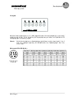
Page 15: ...digital inputs they become TRUE or FALSE when the applied voltage is above or below the switching thresholds of the digital input Wiring of the Mini DIN sockets View of the mating side Socket 1 Socke...

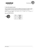
Page 16: ...r has a wired adapter for the direct connection of a dialog unit The connector which is not wired can be used for one s own system extensions Important Only one additional CAN component can be connect...

Reviews: