Seite / Page 14
LED Error
Normally the error LED does not light (logic state 0, potential at pin 13 of the VBB controller).
The LED lights (logic state 1, potential at the controller pin 13 GND) in the case of an error in the
connected controller module (e.g. CAN error) or if the error bit is set in the user program.
Note:
For clarity reasons the output potential of the controller in the simulator or in the diagnostic
box which triggers the Error LED is inverted.
8. Use of external switchboxes and analog boxes at the simulator
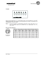
To force input signals switchboxes and analog boxes can be connected to the 7 sockets of the simulator.
With these boxes output states can be simulated to test the software.
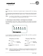
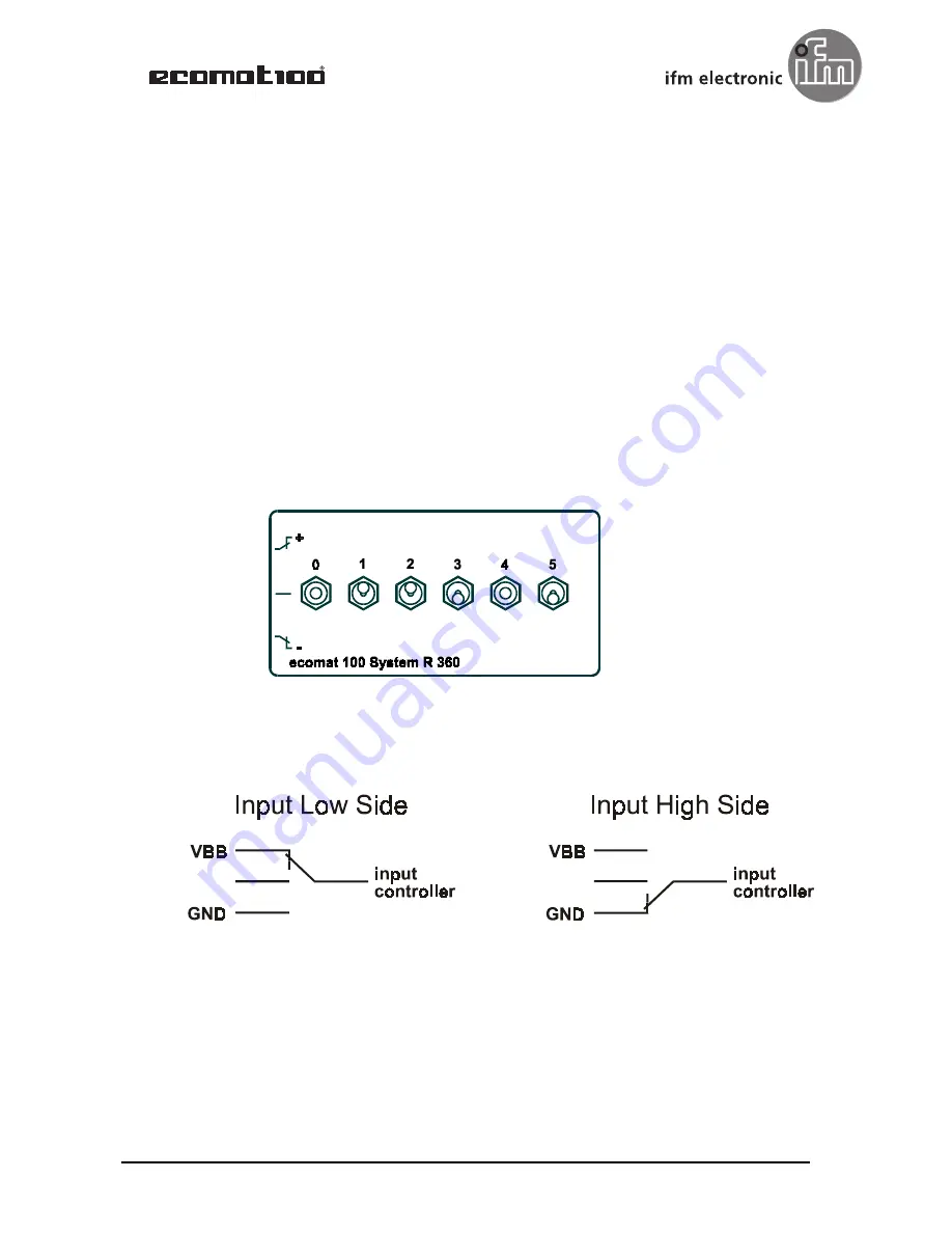
Switchbox
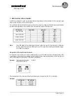
Depending on the configuration of the input the switches have to be connected to GND (-) or VBB (+) to
set the logic state to 1 (on).
Note:
If this switch is in the medium position, the input channel is open. The potential is then set
according to the hardware configuration of the input, i.e. the input channel is FALSE (off).
The input state of the controller
is TRUE (on).
The input state of the controller
is TRUE (on).
Steuerungssysteme


