background image

UK

RFID UHF Sensor

3

1  Preliminary note

This document is intended for specialists� These specialists are people who are 

qualified by their appropriate training and their experience to see risks and to 

avoid possible hazards that may be caused during operation or maintenance of 

the device� The document contains information about the correct handling of the 

device�
Read this document before use to familiarise yourself with operating conditions, 

installation and operation� Keep this document during the entire duration of use of 

the device�

1.1  Symbols used

Instructions

>

Reaction, result

[…]

Designation of keys, buttons or indications

Cross-reference
Important note 

Non-compliance may result in malfunction or interference�
Information 

Supplementary note

2  Safety instructions

2.1  General

These instructions are an integral part of the device� They contain texts and figures 

concerning the correct handling of the device and must be read before installation 

or use�
Observe the operating instructions� Non-observance of the instructions, operation 

which is not in accordance with use as prescribed below, wrong installation or 

incorrect handling can seriously affect the safety of operators and machinery�

2.2  Target group

These instructions are intended for authorised persons according to the EMC and 

low-voltage directives� The device must only be installed, connected and put into 

operation by a qualified electrician�

Summary of Contents for efector 190 DTE820

Page 1: ...Operating instructions RFID UHF Sensor Mid Range DTE820 706386 00 12 2014 UK ...

Page 2: ...Accessories 5 6 Characteristics of the antenna 6 6 1 Reading range and tag shape 6 7 Reading range and selectivity 7 8 Conformity with standards 8 9 Installation 10 9 1 Installation location 10 9 2 Laying of cables 11 9 3 Drilling template 11 9 4 Connections and status indication 12 9 5 GPIO and RS 232 connection 13 9 6 Ethernet and current supply connection 14 10 Typical applications 15 10 1 Acce...

Page 3: ...s buttons or indications Cross reference Important note Non compliance may result in malfunction or interference Information Supplementary note 2 Safety instructions 2 1 General These instructions are an integral part of the device They contain texts and figures concerning the correct handling of the device and must be read before installation or use Observe the operating instructions Non observan...

Page 4: ...here is a risk of fire 2 6 Environmental conditions Do not place the device in the vicinity of heaters do not expose it to direct sunlight and do not operate it in wet environments No objects with open flames must be placed onto the device Protect the device against moisture falling water drops and splashing water Observe the environmental conditions indicated in the technical data sheet There is ...

Page 5: ...sary for the configuration of the DTE820 In this standard the function of the interface between tag and reader is described Further information at www epcglobalinc org The DTE820 can be controlled and evaluated in various ways Software ReaderStart Supplied DLL Access to the reader protocol 4 Items supplied DTE820 RFID UHF sensor CD with demo software example programming DLL and documentation 5 Acc...

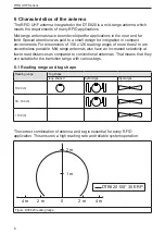
Page 6: ... ranges of more than 2 m are nevertheless possible Mid range antennas also have an increased selectivity at lower read distances as compared to conventional antennas That means that they are suitable for the transition range with various tags 6 1 Reading range and tag shape Reading range Tag shape loop shaped hybrid type dipole type 10 30 cm 30 100 cm 100 cm The correct combination of antenna and ...

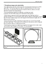
Page 7: ...tags near field tags with an average diameter of 2 cm that mostly couple with the antenna magnetically These tags have the smallest ranges since the magnetic field decreases rapidly with the distance of the antenna The second group consists of hybrid type tags which are a mix of loop shaped and dipole type tags These tags can be activated by the antenna via the magnetic field the electric field or...

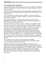
Page 8: ...posure exposure of the general public and local exposure of head and trunk and limbs The WiRa is in general used for applications with a reading area starting with 20 cm At this distance the values are significantly below the maximum SAR values permitted by law In case that use is intended for smaller distances the respective SAR values are numerically calculated The assumptions taken as basis suc...

Page 9: ... DTE820 7 cm 7 cm distance person and DTE820 General public Limit values head and trunk 2 W kg Limit values local limbs 4 W kg Pin 0 32 W Pin 1 84 W Occupational exposure Limit values head and trunk 10 W kg Pin 1 75 W Pin 1 84 W Occupational exposure Limit values local limbs 20 W kg Pin 1 84 W ...

Page 10: ... a mounting bracket use a square shaped metal plate with the dimensions 16 x 16 cm see Figure 3 Avoid conductive objects such as tanks with liquids in the vicinity of the installation location The objects influence the performance of the antenna Ensure sufficient heat dissipation at the installation location The maximum operating temperature indicated in the data sheet must not be exceeded min 70 ...

Page 11: ...figure on the right Avoid cable loops around and on the sensor see figure on the left Figure Incorrectly laid cable Figure Correctly laid cable 9 3 Drilling template The DTE820 is fixed to the ground using 4 screws The bore hole distances are indicated in the following drawing A fixture allowing installation on a mast is available as accessory 110 140 4 5 X ...

Page 12: ...tion 2 colour LED red green 3 Ethernet and current supply connection M12 female 4 poles D coded Load digital inputs and outputs with max 0 5 A Load all digital inputs and outputs used with max 1 5 A in total When using the auxiliary voltage 24 V DC pin7 load the digital inputs and outputs with max 1 1 A Load digital inputs and outputs with max 30 V DC Use LPS Limits Power Source or NEC class 2 pow...

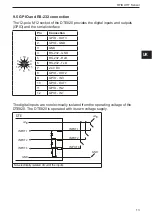
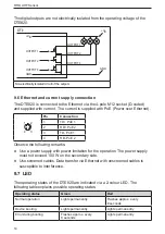
Page 13: ...ction 1 GPIO OUT3 2 GPIO GND 3 GND 4 RS 232 GND 5 RS 232 RxD 6 RS 232 TxD 7 24 V DC 8 GPIO OUT2 9 GPIO IN3 10 GPIO OUT1 11 GPIO IN2 12 GPIO IN1 The digital inputs are not electrically isolated from the operating voltage of the DTE820 The DTE820 is operated with its own voltage supply DTE UB GND INPUT 1 INPUT 2 INPUT 1 INPUT 2 UB GND INPUT 3 INPUT 3 Non electrically isolated circuit of the inputs ...

Page 14: ...ion 1 TD PoE 1 2 RD PoE 2 3 TD PoE 1 4 RD PoE 2 Observe the following remarks Use a power supply with power limitation for the operation The power supply must not exceed 100 W on the secondary side Use screened cables Data transfer via Ethernet with unscreened cables is susceptible to interference 9 7 LED The operating states of the DTE820 are indicated via a 2 colour LED The following table expla...

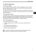
Page 15: ... used for RFID automation applications with a defined reading area and high selectivity Of great advantage is the possibility to detect far field tags with the ANT805 antenna individually and to read the same tags with DTE820 at other reading stations at larger distances in multi tag operation 10 3 Further applications Further typical applications for DTE820 Logistics applications when installed o...

Page 16: ...o Frequency Identification SAR Specific Absorption Rate UHF Ultra High Frequency 12 Maintenance repair and disposal The device does not contain any components that need to be maintained Do not open the device The device must only be repaired by the manufacturer Dispose of the device in accordance with the national environmental regulations ...

Reviews: