


2
1 Function and features
The flow monitor monitors liquid media. It senses whether there is a preset flow
and provides a switching signal.
•
The switch point can be set: 10...60 cm/s in steps of 5 cm/s). This value is valid
for water and installation in pipes 4". It changes with other media/other pipe
diameters.
2 Installation
The sensor tip must be completely immersed in the medium.
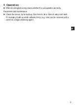
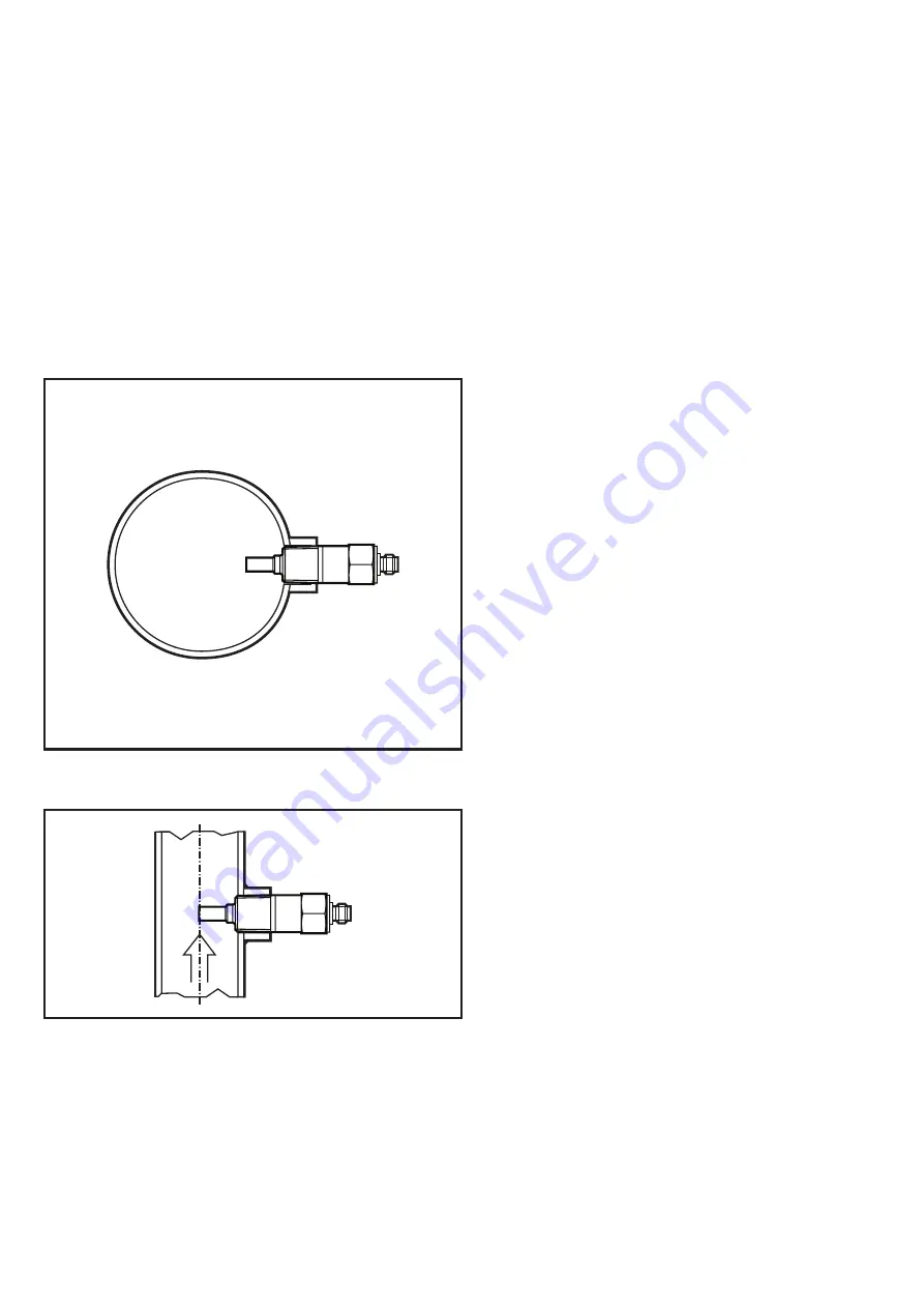
►
In the case of horizontal pipes
mount the unit from the side, if
possible.
•
When the unit is to be mounted at
the bottom of the pipe, it should
be free from deposits.
•
When the unit is to be mounted
at the top of the pipe, it should be
completely filled with the medium
to be monitored.
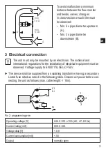
►
In the case of vertical pipes mount
the unit in a place where the
medium flows upwards.
Use only a correctly-sized spanner (or torque wrench) to fasten the unit.
Tightening torque max. 100 Nm (with stainless steel adapter) or ANSI B1.20.1.


