background image

3

UK

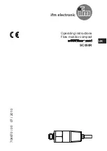
To avoid malfunction a minimum 

distance between the flow monitor 

and bends, valves, changes 

in cross-section or such like must 

be observed:

• 

Min. 5 x pipe diameter upstream 

(A).

• 

Min. 3 x pipe diameter 

downstream (B).

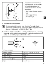
3  Electrical connection

The unit must only be mounted by an electrician. The national and  

international regulations for the installation of electrical equipment must be 

observed. Voltage supply to EN 50178, SELV, PELV. 


The device shall be supplied from an isolating transformer having a secondary 

Listed fuse rated as noted in the following table. Disconnect power before con-

necting the unit as follows (max. cable length: < 10m).

Pin 2: programming wire

Operating voltage [V]

24 AC / DC ± 15% (AC: 47...63 Hz)

Current rating [mA]

80 AC / DC

Voltage drop [V]

< 0,8

Current consumption [mA]

< 50

Output

normally open

Summary of Contents for Efector 300 SC050R

Page 1: ...Operating instructions Flow monitor compact SC050R 704870 00 07 2010 UK ...

Page 2: ...ompletely immersed in the medium In the case of horizontal pipes mount the unit from the side if possible When the unit is to be mounted at the bottom of the pipe it should be free from deposits When the unit is to be mounted at the top of the pipe it should be completely filled with the medium to be monitored In the case of vertical pipes mount the unit in a place where the medium flows upwards U...

Page 3: ...l and international regulations for the installation of electrical equipment must be observed Voltage supply to EN 50178 SELV PELV The device shall be supplied from an isolating transformer having a secondary Listed fuse rated as noted in the following table Disconnect power before con necting the unit as follows max cable length 10m Pin 2 programming wire Operating voltage V 24 AC DC 15 AC 47 63 ...

Page 4: ... C the switching status can change In the time windows D E F the output is used for feedback signals table below It does not react to flow changes Time window Operation A Inititalisation of the setting operation B Confirmation of the initialisation C Switch point setting Signal UB at pin 2 s 10 15 20 55 60 results in SP cm s 10 15 20 55 60 D Last switching status from C is maintained internal moni...

Page 5: ...ck whether the unit operates correctly Recommended maintenance Check the sensor tip for build up from time to time Clean it with a soft cloth If necessary build up which adheres firmly e g lime can be removed with a common vinegar cleansing agent ...

Reviews: