UK
Installation Guide O2Ixxx
7
O
O
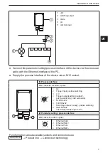
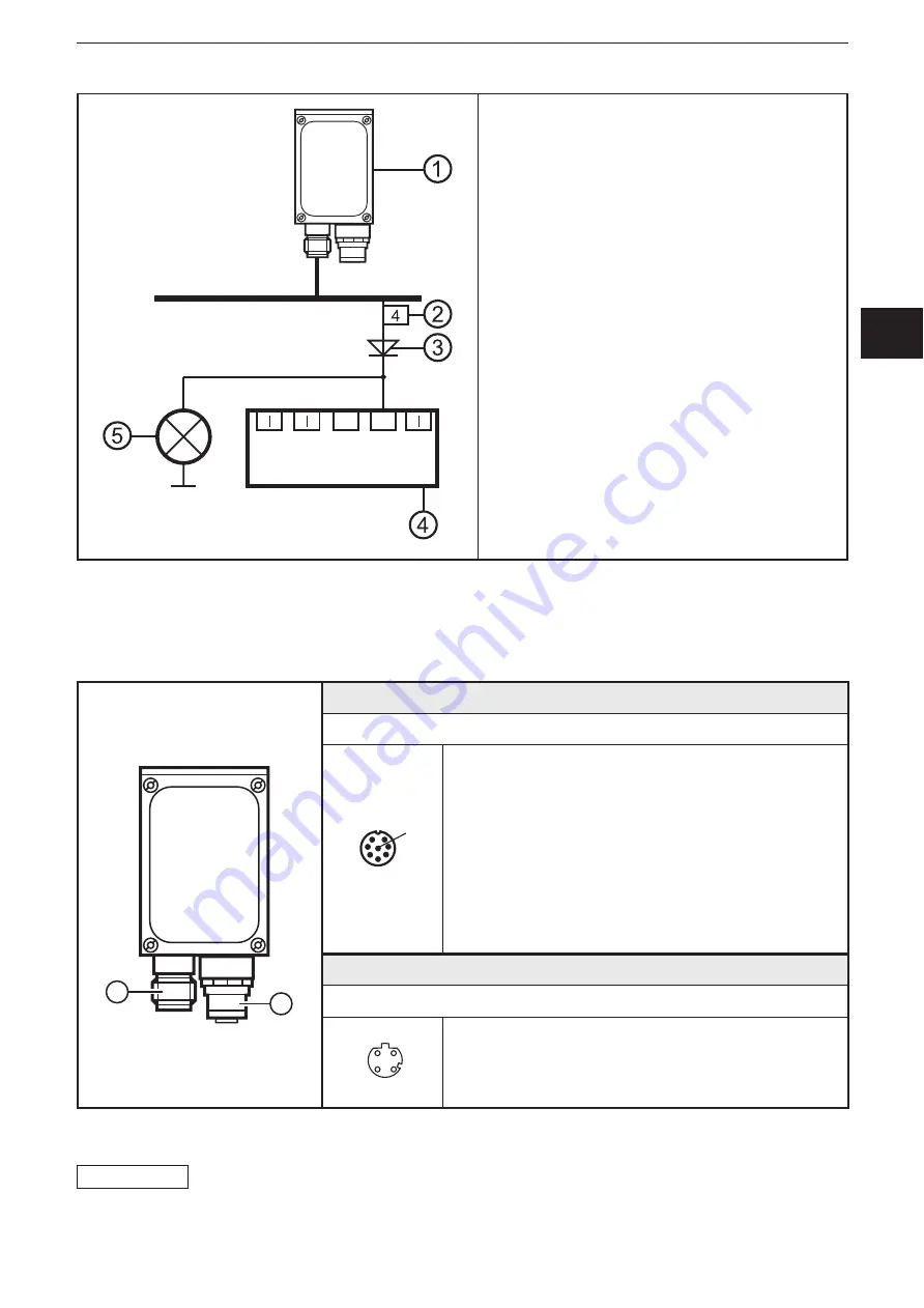
1 unit
2 switching output
3 diode
4 plc
5 common load
● Connect the parameter setting/process interface of the device via the crossover
cable with the Ethernet interface of the PC�
● Supply the process interface of the device via an M12 socket�
(1) Process interface
M12 connector, A-coded, 8 poles
1 U+
2 Trigger input, positive switching
3 0 V
4 Trigger output/switching output 1,
positive switching (code evaluation)
5 RxD RS-232
6 TxD RS-232
7 Switching output 2 (ready), positive switching
8 GND RS-232
(electrically isolated up to 50 V)
(2) Parameter setting / process interface
M12 socket, D-coded, 4 poles
1 Ethernet TxD +
2 Ethernet RxD +
3 Ethernet TxD -
4 Ethernet RxD -
For information about available sockets and connectors see
www�ifm�com
→ Product line → Connection technology


