background image

Image processing system

OVP800 M03975

7

4 Installation

115

92,5

58

98,7

M5

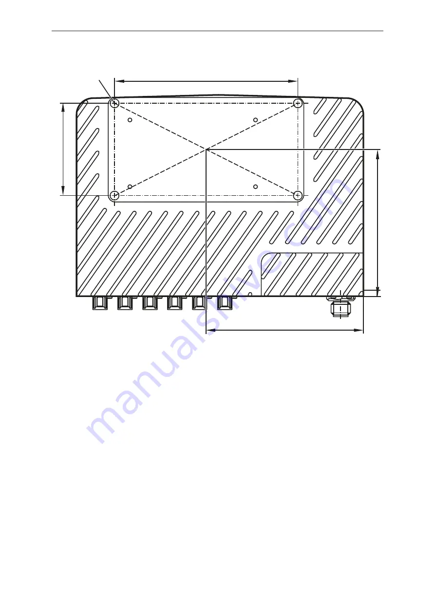
Fig. 1: Rear of the unit with the threaded M5 holes

Mounting the unit:

u

Mount the unit on a mounting plate using the 4 threaded M5 holes.

w

Observe the maximum tightening torque of 5.5 Nm for the threaded holes.

w

The unit must rest on the mounting plate. Thermal contact is necessary for heat distribution.

u

Connect the housing of the unit and the connected sensors to the same earth.

w

If no connection to the same earth is possible: Mount the unit and the sensors isolated from the
earth.

u

Avoid installation in heavily polluted environments.

Summary of Contents for OVP800

Page 1: ...Operating instructions Image processing system OVP800 M03975 11423775 00 11 2021 GB...

Page 2: ...formation 3 1 5 Open source information 3 2 Safety instructions 5 2 1 Cyber security 5 3 Intended use 6 3 1 Application area 6 4 Installation 7 5 Electrical connection 8 5 1 Wiring 9 6 Operating and d...

Page 3: ...0 1 chapter 9 4 Limited energy circuit Device of protection class III Only for operation in PELV circuits 1 4 Legal and copyright information All rights reserved by ifm electronic gmbh No part of thes...

Page 4: ...lied warranty of MERCHANTABILITY or FITNESS FOR A PARTICULAR PURPOSE See the GNU General Public License and the GNU Lesser General Public License for more details The responsibility of ifm electronic...

Page 5: ...the corresponding applications and environmental conditions without any restrictions Only use the product for its intended purpose Intended use If the operating instructions or the technical data are...

Page 6: ...ds 3 1 Application area The device safety is rated for use under the following operating conditions according to EN IEC 61010 2 201 indoor use altitudes up to 2000 m relative air humidity up to max 90...

Page 7: ...les w Observe the maximum tightening torque of 5 5 Nm for the threaded holes w The unit must rest on the mounting plate Thermal contact is necessary for heat distribution u Connect the housing of the...

Page 8: ...eclosing electromechanical device Separate the circuit from other non energy limited circuits by at least basic insulation The separation of external circuits must comply with IEC 61010 2 201 Figure 1...

Page 9: ...ce 2 0 4 USB interface 5 Sensor port 0 to port 5 from left to right Power supply CAN M12 connector A coded 5 poles 4 2 1 3 5 1 screen 2 24 V 3 GND 4 CAN 5 CAN USB 2 0 mini USB interface 4 5 3 2 1 1 VB...

Page 10: ...tion on Device switched on off Device switched off Status LED Status LED green Status LED red Description on off Normal operation software is being up dated off on General error off Flashes Operation...

Page 11: ...m OVP800 M03975 11 7 Parameter setting The camera parameters can be set in two ways ifmVisionAssistant software available for download www ifm com Code examples available for download in the developer...

Page 12: ...sition and data processing are paused The overtemperature protection becomes active in case of u high ambient temperature u high CPU load or u insufficient thermal contact w The overtemperature protec...

Page 13: ...nce free Cleaning agents containing solvents and silicone may damage the unit u Only use cleaning agents without solvents and silicone Repair Only the manufacturer is allowed to repair the unit Dispos...

Page 14: ...standards For approvals and standards the following information is available Test standards and regulations documentation ifm com EU declaration of conformity and approvals documentation ifm com Note...

Reviews: