mobileIoT gateway
CR3158
17
6 Electrical connection
6.1 Connectors
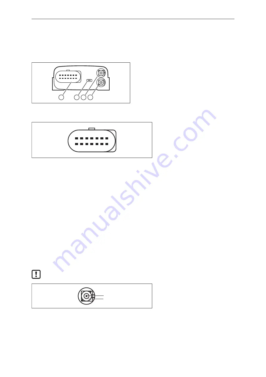
2 3 4
1
1: Micro Timer II connector, 14-pin
(CAN, supply, inputs, outputs)
2: USB socket (Micro-AB type)
3: FAKRA connector, D-coded
4: FAKRA connector, C-coded
6.1.1 Operating voltage, CAN interface, inputs and outputs
1
2
13
14
Fig. 2: Micro Timer II connector, 14-pin
1:
VCC / clamp 30 (supply)
2:
CAN3_L (CAN interface 3 (low) bidirectional)
3:
GND / clamp 31 (supply)
4:
analogue input 1
5:
analogue input 2
6:
analogue input 3
7:
digital output
8:
digital output / clamp 15 (input, ignition signal)
9:
CAN3_H (CAN interface 3 (high) bidirectional)
10: CAN2_GND
11: CAN2_H (CAN interface 2 (high) bidirectional)
12: CAN2_L (CAN interface 2 (low) bidirectional)
13: CAN1_H (CAN interface 1 (high) bidirectional)
14: CAN1_L (CAN interface 1 (low) bidirectional)
6.1.2 GNSS antenna connection
The GNSS antenna connection is supplied with a voltage of approx. 3.3 V and can supply active
antennas with a maximum current of 40 mA. The connection is short-circuit-proof and detects that an
antenna is present when the current is greater than approx. 2 mA.
Make sure that the unit is switched off during installation.
1
2
Fig. 3: FAKRA connector, C-coded
1:
Signal — GNSS signal, supply voltage 3.3 V
2:
GND — shielding / housing


