RFID compact unit
DTE601 DTE602 DTE604 DTE605
17
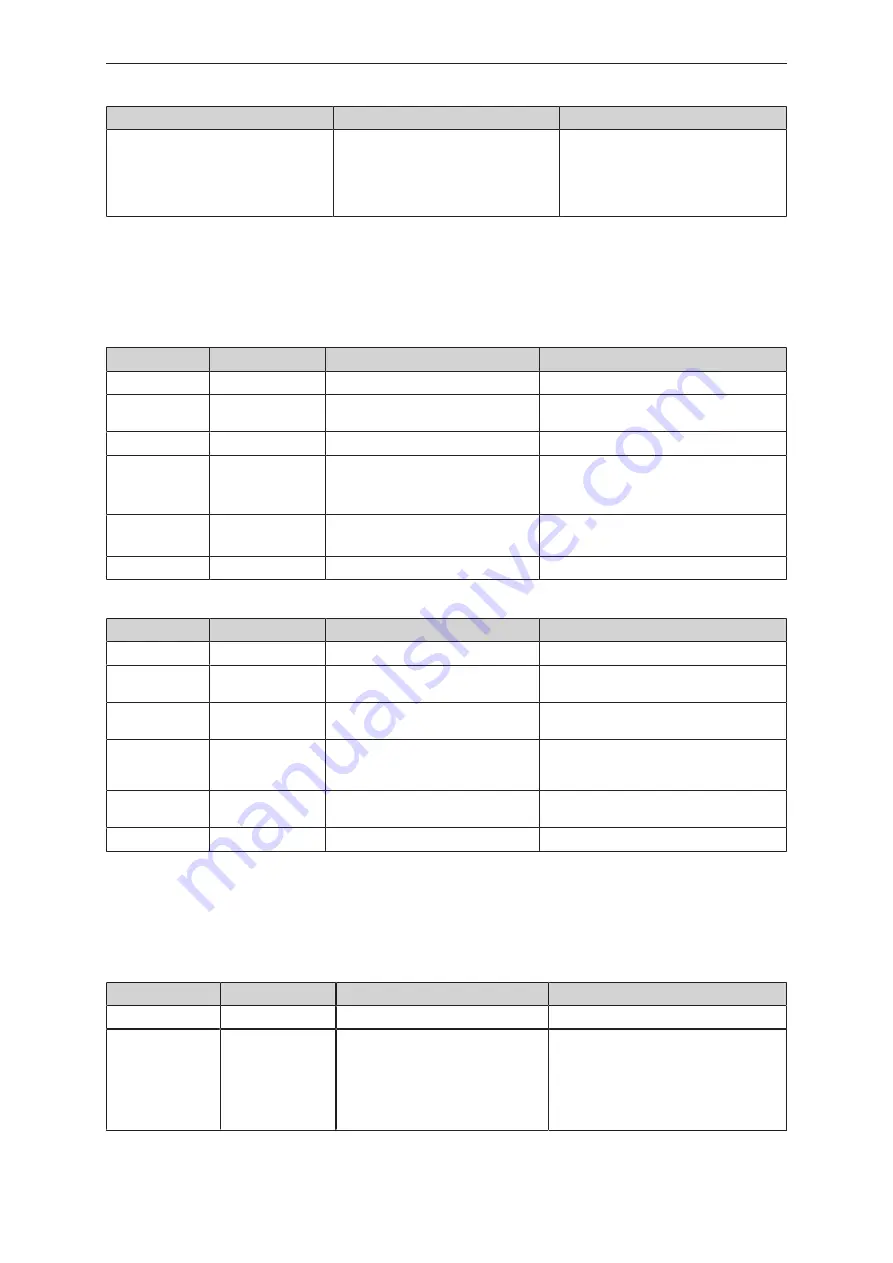
LED
State
Note
Power LED (green) on
The LEDs of the signal bar (yellow) are
on one after the other. Then LED 4 of
the signal bar (yellow) flashes at 8 Hz.
Reset to factory settings.
-
8.1 Display elements DTE601
The following tables only apply to the DTE601 device.
LED SF
LED red
LED green
State
Note
off
off
no voltage supply
Check the voltage supply
off
flashes
“Node flash test”, initiated by the
PROFINET IO controller
-
off
on
Normal operation
-
flashes
off
Error at channel level
• Overload
• Temperature
• Internal error
on
off
Error at device level
• Undervoltage
• Temperature
flashes
flashes
Self-test
Starting phase of the device
LED BF
LED red
LED green
State
Note
off
off
no voltage supply
Check the voltage supply
off
flashes
PROFINET IO controller is in STOP
mode
-
off
on
PROFINET IO controller is in RUN
mode
-
flashes
off
Connection to the PROFINET IO con-
troller is established, no valid configu-
ration
Check configuration
on
off
No connection to the PROFINET IO
controller
Check connection
flashes
flashes
Self-test
Starting phase of the device
8.2 Display elements DTE602
The following tables only apply to the DTE602 device.
LED Mod (module status)
LED red
LED green
State
Note
off
off
no voltage supply
Verify voltage supply.
off
flashes
Ready for operation
The device is not configured. There is no
exchange of data:
u
Check the connection of the Ethernet/
IP scanner.
u
Check the parameter setting of the
configuration assembly.