DTE601 DTE602 DTE604 DTE605
RFID compact unit
16
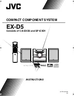
8 Operating and display elements
1
2
Fig. 3: Operating and display elements
1 1x LED power (green)
4x LED signal bar (yellow)
2x LED field bus (green/red)
2 Sensing face
The following table applies to all units.
State
Power LED (green)
LED signal bar (yellow)
Voltage supply OK (18 V ≤ UPWR ≤ 36 V)
on
off
Antenna (HF field) is deactivated
flashes at 2 Hz
off
ID tag read / written successfully
on
flashes twice
ID tag read / written incorrectly
on
flashing quickly
The maximum receive signal strength depends on the type of the ID tag.
If the ID tag has a high receive signal strength, all LEDs of the signal bar are on.
w
The response of the LEDs of the signal bar is adjustable.
LED LINK/ACT ETH 1 / ETH 2
LED green
LED yellow
State
Note
off
off
No connection to an Ethernet
counterpart.
Link status: “No Link”
on
off
Connection to Ethernet coun-
terpart exists, no data ex-
change.
Link status: “Link”, “No traffic”
on
flashes sporadically
Connection to Ethernet coun-
terpart exists, data exchange
running.
Link status: “Link”, “Traffic”
Special device LED indicators
LED
State
Note
Power LED (green) on
LEDs of signal bar (yellow) flashing at 8
Hz.
Device is in the service mode “emergen-
cy system started”.
A firmware update is necessary and can
be executed via the web server.
Power LED (green) on
LEDs of signal bar (yellow) flashing at 8
Hz.
Major error, device has to be returned.
Hardware fault or permanent data in the
device are corrupt.