182
ifm
Device Manual SmartSPS AC14 with EtherNet/IP interface (AC1421, AC1422), Firmware 3.1.2
2015-11-30
Appendix
Fieldbus EtherNet/IP
>
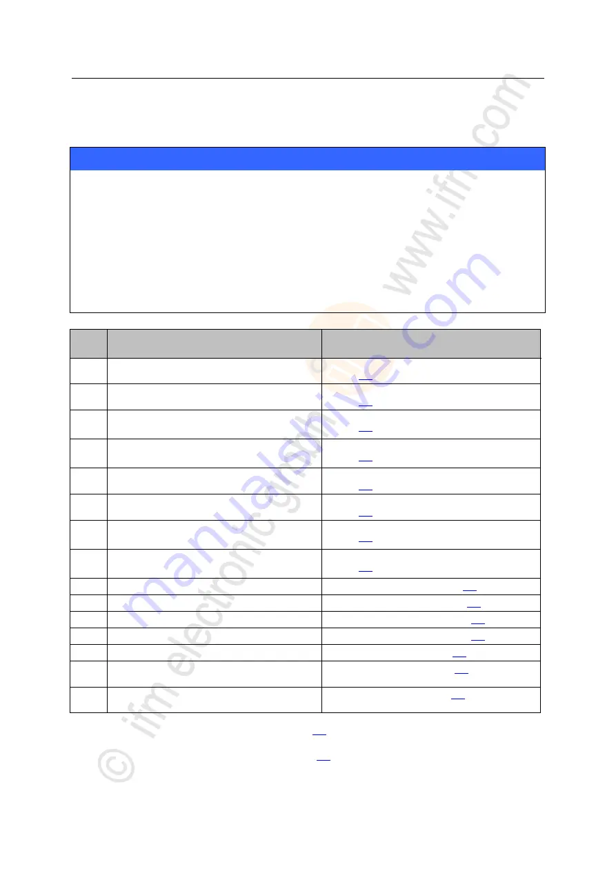
EtherNet/IP modules
12419
NOTICE
Risk of data loss!
For the transmission of cyclic process data between the device and the EtherNet/IP PLC, a limited
number of data words is available for each direction of transmission:
Input data (= modules 1, 3, 5, 7, 9, 10, 13, 14): 248 words
Output data (= modules 2, 4, 6, 8, 11, 12, 15): 248 words
If the EtherNet/IP modules have been parameterised in such a way that the cyclic input and output
data comprise more than 248 words per direction of transmission, any data from the 249th word will
not be transmitted and will therefore be lost.
► Parameterise the EtherNet/IP modules in a way to ensure that the input and output data do not
exceed the maximum number of words to be transmitted!
Slot
Description
Further information
1
Digital input data single or A slaves, AS-i master 1
→
Slot 1 – Digital input data single or A slaves, AS-i master 1
(
→ page
2
Digital output data single or A slaves, AS-i master 1
→
Slot 2 – Digital output data single or A slaves, AS-i master 1
(
→ page
3
Digital input data single or A slaves, AS-i master 2
(only available for devices with 2 AS-i masters)
→
Slot 3 – Digital input data single or A slaves, AS-i master 2
(
→ page
4
Digital output data single or A slaves, AS-i master 2
(only available for devices with 2 AS-i masters)
→
Slot 4 – Digital output data single or A slaves, AS-i master 2
(
→ page
5
Digital input data B slaves, AS-i master 1
→
Slot 5 – Digital input data B slaves, AS-i master 1
(
→ page
6
Digital output data B slaves, AS-i master 1
→
Slot 6 – Digital output data B slaves, AS-i master 1
(
→ page
7
Digital input data B slaves, AS-i master 2
(only available for devices with 2 AS-i masters)
→
Slot 7 – Digital input data B slaves, AS-i master 2
(
→ page
8
Digital output data B slaves, AS-i master 2
(only available for devices with 2 AS-i masters)
→
Slot 8 – Digital output data B slaves, AS-i master 2
(
→ page
9
Analogue input data of up to 31 slaves, range 1*
→
Slot 9 – Analogue input data
(
10
Analogue input data of up to 31 slaves, range 2*
→
Slot 10 – Analogue input data
(
→ page
11
Analogue output data of up to 31 slaves, range 1**
→
Slot 11 – Analogue output data
(
→ page
12
Analogue output data of up to 31 slaves, range 2**
→
Slot 12 – Analogue output data
(
→ page
13
Diagnostic data
→
Slot 13 – Diagnostic data
(
→ page
14
Data from the device-internal PLC to the EtherNet/IP
PLC
→
Slot 14 – Inputs from PLC
(
→ page
15
Data from the EtherNet/IP PLC to the device-internal
PLC
→
Slot 15 – Outputs to PLC
(
→ page
* ...
Define the number of analogue channels and the slave number by means of the device parameters [analogue
channels/I-slave] (
→
Device-specific parameters
(
→ page
** ...
Define the number of analogue channels and the slave number by means of the device parameters [analogue
channels/O-slave] (
→
Device-specific parameters
(
→ page


