187
ifm
Device Manual SmartSPS AC14 with EtherNet/IP interface (AC1421, AC1422), Firmware 3.1.2
2015-11-30
Appendix
Fieldbus EtherNet/IP
>
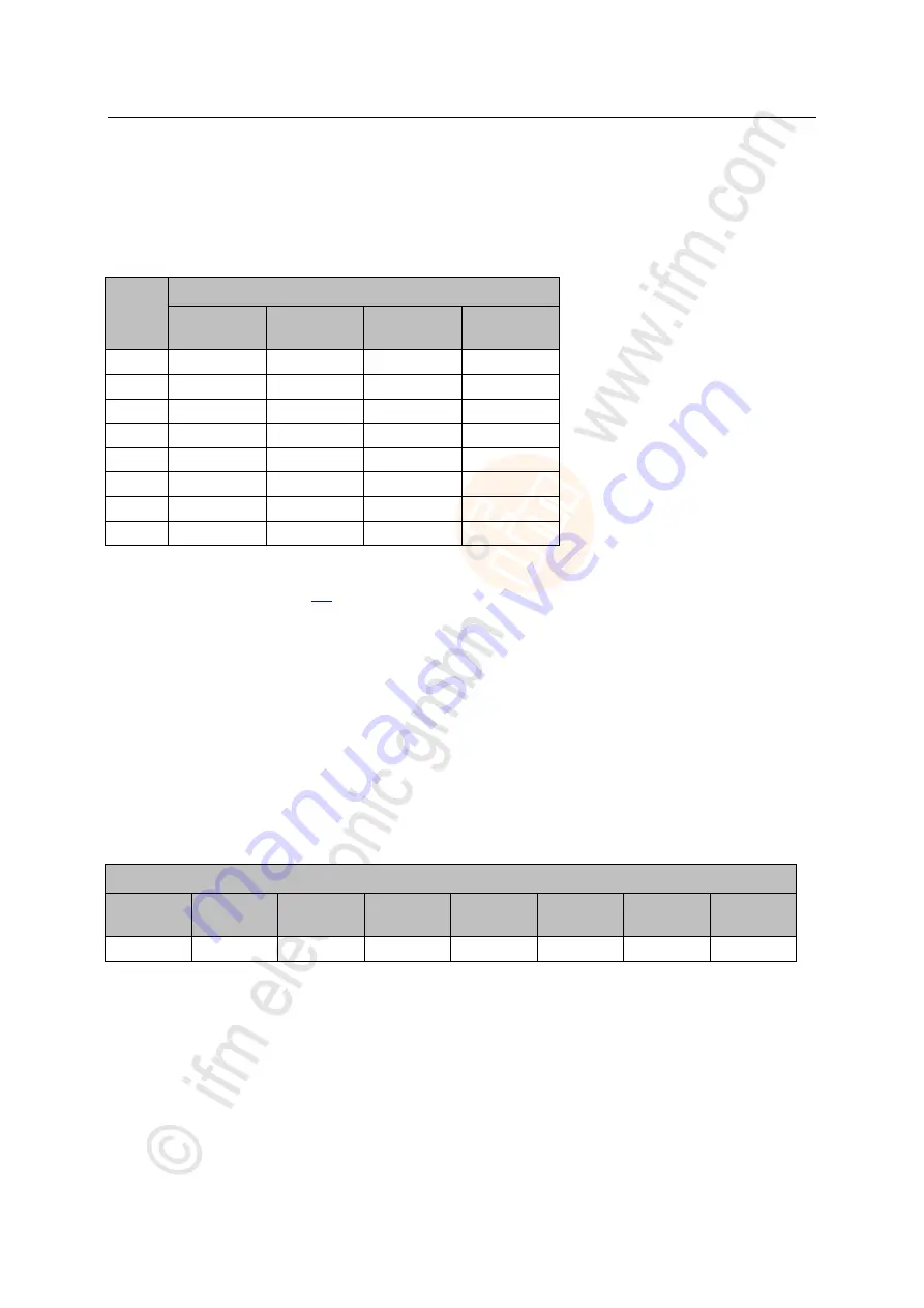
Mapping of the digital input/output data
13447
This table illustrates the mapping of digital input/output data of the individual slaves to the bytes of the
transmitted words:
Word
AS-i slave addresses
Bits
15...12
Bits
11...8
Bits
7...4
Bits
3...0
1
M flags*
1(A) / 1B
2(A) / 2B
3(A) / 3B
2
4(A) / 4B
5(A) / 5B
6(A) / 6B
7(A) / 7B
3
8(A) / 8B
9(A) / 9B
10(A) / 10B
11(A) / 11B
4
12(A) / 12B
13(A) / 13B
14(A) / 14B
15(A) / 15B
5
16(A) / 16B
17(A) / 17B
18(A) / 18B
19(A) / 19B
6
20(A) / 20B
21(A) / 21B
22(A) / 22B
23(A) / 23B
7
24(A) / 24B
25(A) / 25B
26(A) / 26B
27(A) / 27B
8
28(A) / 28B
29(A) / 29B
30(A) / 30B
31(A) / 31B
Legend:
*
...
The master flags (M flags) are only transmitted in the digital input data
(
→
Table: Master flags
(
→ page
>
Example: structure of the digital input data
13450
Task:
The digital input data of slaves 1A, 3 and 6A of AS-i master 1 are to be transmitted.
Solution:
Slot: 1
Module configuration:
01 ... 07
Data length: 2 words
The following table shows in which positions of the two word sized data block the digital input data of
the slaves are transmitted:
Data block (2 words)
Bits
31...28
Bits
27...24
Bits
23...20
Bits
19...16
Bits
15...12
Bits
11...8
Bits
7...4
Bits
3...0
1A
3
6A


