MK59xx
Cylinder sensor with IO-Link
20
•
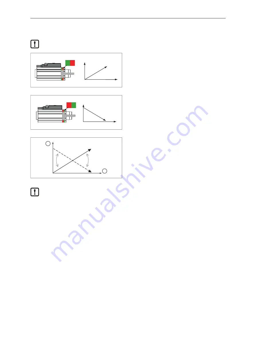
The process data value (PDV) increases as the target moves away from the sensor.
u
Set the signal direction so that the sensor behaves according to the specified function class
"Object Detection".
S N
Fig. 8: Cylinder rod North Pole direction
The signal increases when the cylinder rod is
extended.
The sensor behaves according to the specified
function class "Object Detection".
N S
Fig. 9: Cylinder rod South Pole direction
The signal decreases when the cylinder rod is
extended.
u
Inverting the signal direction.
1
2
Fig. 10: Signal inversion
1:
PDV
2:
Magnet position
After a [Teach In Application], the LEDs for the switch point display may be inverted. By
inverting the signal direction before a [Teach In Application], the assignment of the LEDs can
also be changed.
Parameter setting:
u
Select [Parameter] > [Signal] > [Signal direction] to set the signal direction.
9.6 Output polarity of the switching outputs
The parameter [P-n] can be used to select whether the outputs are plus-switching or negative-
switching.
u
Select [Parameters] > [Setup].
u
Select [P-n] and set [PnP] or [nPn].
9.7 Output off
The output signal for output OUT1 or output OUT2 can be switched off in two ways:
•
[OFF]: The physical output OUTx becomes highly resistive so that no signal can be output. The
status of the switching signal channels SSC1.x is still transmitted via the IO-Link interface.
•
[Deactivated]: The switching signal channel is deactivated, i.e. the switching state is permanently in
the inactive state: With [High active] setting permanently "low", with [Low active] setting
permanently "high".
u
Call up [Parameters] > [Output Configuration].
u
Select [oux] and set [OFF].


