background image


POC2502 Series User Manual 

119 

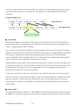
ports. If the packet doesn't have an 802.1Q VLAN tag, the port will not alter the packet. Thus, 

all packets received by and forwarded by an untagging port will have no 802.1Q VLAN 

information. (Remember that the PVID is only used internally within the Switch). Untagging is 

used to send packets from an 802.1Q-compliant network device to a non-compliant network 

device. 


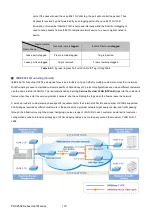
Frame Income 

Frame Leave 

Income Frame is 

tagged


Income Frame is 

untagged


Leave port is tagged 

Frame remains tagged 

Tag is inserted 

Leave port is untagged 

Tag is removed 

Frame remain untagged 

Table 4-5-1:

 Ingress / Egress Port with VLAN VID Tag / Untag Table 


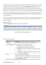
IEEE 802.1Q Tunneling (Q-in-Q) 

IEEE 802.1Q Tunneling (QinQ) is designed for service providers carrying traffic for multiple customers across their networks. 

QinQ tunneling is used to maintain customer-specific VLAN and Layer 2 protocol configurations even when different customers 

use the same internal VLAN IDs. This is accomplished by inserting 

Service Provider VLAN (SPVLAN)

 tags into the customer’s 

frames when they enter the service provider’s network, and then stripping the tags when the frames leave the network.   

A service provider’s customers may have specific requirements for their internal VLAN IDs and number of VLANs supported. 

VLAN ranges required by different customers in the same service-provider network might easily overlap, and traffic passing 

through the infrastructure might be mixed. Assigning a unique range of VLAN IDs to each customer would restrict customer 

configurations, require intensive processing of VLAN mapping tables, and could easily exceed the maximum VLAN limit of 

4096.   


Summary of Contents for POC2502 Series

Page 1: ...1 POC2502 Series User Manual P N 1073045 REV B ISS 18MAY22...

Page 2: ...if not installed and used in accordance with the instruction manual may cause harmful interference to radio communications Operation of this equipment in a residential area is likely to cause harmful...

Page 3: ...typroducts com Australian New Zealand https firesecurityproducts com au Product documentation Please consult the following web link to retrieve the electronic version of the product documentation The...

Page 4: ...POC2502 Series User Manual 1...

Page 5: ...istration Console 40 3 4 Web Management 41 3 5 SNMP based Network Management 42 3 6 IFS Smart Discovery Utility 42 4 WEB CONFIGURATION 44 4 1 Main Web Page 47 4 1 1 Save Button 48 4 1 2 Configuration...

Page 6: ...125 4 5 9 Protocol VLAN Port Setting 126 4 5 10 GVRP Setting 128 4 5 11 GVRP Port Setting 130 4 5 12 GVRP VLAN 132 4 5 13 GVRP Statistics 132 4 5 14 VLAN setting example 134 4 5 14 1 Two Separate 802...

Page 7: ...4 9 1 802 1X 213 4 9 1 1 Understanding IEEE 802 1X Port based Authentication 214 4 9 1 2 802 1X Setting 217 4 9 1 3 802 1X Port Setting 218 4 9 1 4 Guest VLAN Setting 220 4 9 1 5 Authenticated Host 22...

Page 8: ...Remote Device 304 4 12 6 MED Network Policy 306 4 12 7 MED Port Setting 309 4 12 8 LLDP Overloading 312 4 12 9 LLDP Statistics 313 4 13 Diagnostics 314 4 13 1 Cable Diagnostics 315 4 13 2 Ping 317 4...

Page 9: ...POC2502 Series User Manual 6 5 4 Store and Forward 343 5 5 Auto Negotiation 345 6 TROUBLESHOOTING 346 APPENDIX A 348 A 1 Switch s RJ45 Pin Assignments 348 A 2 10 100Mbps 10 100BASE TX 348...

Page 10: ...of this manual to ensure the accuracy of its contents Carrier assumes no responsibility for errors or omissions Product warnings YOU UNDERSTAND THAT A PROPERLY INSTALLED AND MAINTAINED ALARM SECURITY...

Page 11: ...tery is replaced by an incorrect type Dispose of batteries according to the instructions Contact your supplier for replacement batteries Warranty disclaimers CARRIER HEREBY DISCLAIMS ALL WARRANTIES AN...

Page 12: ...rpose it was designed for refer to the data sheet and user documentation For the latest product information contact your local supplier or visit us online at firesecurityproducts com The system should...

Page 13: ...P PoE over Coaxial Managed Switch POC Managed Switch is used as an alternative name in this user s manual 1 1 Packet Contents Open the box of the POC Managed Switch and carefully unpack it The box sho...

Page 14: ...gabit copper ports and 2 extra 100 1000BASE X SFP fiber slots As an advanced PoE switch the IFS POC2502 Managed Switch features intelligent PoE functions to improve the availability of critical applic...

Page 15: ...twork with BNC T connector for sharing four nodes per port when needed Built in Unique PoE Functions for Powered Devices Management As a managed PoE switch for surveillance wireless and VoIP networks...

Page 16: ...you to enable or disable PoE power feeding for each PoE port during specified time intervals and it is a powerful function to help SMBs or enterprises save power and money It also increases security...

Page 17: ...8Gbps fat pipe and supports fail over as well Also the Link Layer Discovery Protocol LLDP is the Layer 2 Protocol included to help discover basic information about neighboring devices on the local bro...

Page 18: ...supporting SSH SSL and SNMP v3 connections which encrypt the packet content at each session Flexibility and Long distance Extension Solution The IFS POC2502 Managed Switch provides two Gigabit TP int...

Page 19: ...ter explains how to troubleshoot of the POC Managed Switch Appendix A The section contains cable information of the POC Managed Switch 1 4 Product Features Physical Port 100Mbps BNC female ports with...

Page 20: ...TP Multiple Spanning Tree Protocol STP BPDU Guard BPDU Filtering and BPDU Forwarding Supports Link Aggregation IEEE 802 3ad Link Aggregation Control Protocol LACP Cisco ether channel static trunk Maxi...

Page 21: ...gement IPv4 and IPv6 dual stack management Switch management interface Web switch management Telnet command line interface SNMP v1 v2c and v3 SSH SSL secure access User privilege levels control Built...

Page 22: ...ors POC2502 16CXP 2T 2S 16 x BNC female connectors Long Reach PoE over coaxial PSE Power Source Equipment BNC center pole DC Hi BNC shield DC Lo Power Output Per port 54V DC 36 watts max Per port 52V...

Page 23: ...e copper wire and environmental factors The performance result above is based on the testing via the RG 6 U coaxial cable TX POC2502 8CXP 2T 2S to POC252 1CX 1P RX POC252 1CX 1P to POC2502 8CXP 2T 2S...

Page 24: ...ort trunk Spanning Tree Protocol STP RSTP MSTP IGMP Snooping IGMP v2 v3 Snooping IGMP Querier Up to 256 multicast groups MLD Snooping MLD v1 v2 Snooping up to 256 multicast groups Access Control List...

Page 25: ...Line IEEE 802 3 10BASE T IEEE 802 3u 100BASE TX 100BASE FX IEEE 802 3z Gigabit SX LX IEEE 802 3ab Gigabit 1000T IEEE 802 3x flow control and back pressure IEEE 802 3ad port trunk with LACP IEEE 802 1D...

Page 26: ...1 1100 335 22 3 21 2 12 1200 366 21 8 20 6 13 1300 396 21 2 20 0 14 1400 427 20 7 19 8 15 1500 457 19 7 18 9 16 1600 488 19 3 18 5 17 1700 518 18 9 18 1 18 1800 549 18 2 18 0 19 1900 579 17 5 17 0 20...

Page 27: ...2 8 12 1 7 700 213 10 6 10 5 8 800 244 9 5 10 1 9 900 274 9 3 8 7 10 1000 305 7 9 7 4 11 1100 335 7 1 6 7 12 1200 366 6 4 5 8 13 1300 396 5 5 5 3 14 1400 427 5 4 5 1 15 1500 457 4 9 4 6 Above PoE outp...

Page 28: ...C Managed Switch Figure 2 1 1A 2 1 1B shows the front panel of the POC Managed Switch Front Panel Figure 2 1 1A POC2502 8CXP 2T 2S Front Panel Front Panel Figure 2 1 1B POC2502 16CXP 2T 2S Front Panel...

Page 29: ...mmary table of the Reset button functions Reset Button Pressed and Released Function 5 sec System Reboot Reboot the POC Managed Switch 5 sec Factory Default Reset the POC Managed Switch to the Factory...

Page 30: ...or Function LNK ACT Green Lights To indicate the link through that port is successfully established Blink To indicate that the switch is actively sending or receiving data over that port 1000 Orange L...

Page 31: ...cally adjusts to line power in the range of 100 240V AC and 50 60 Hz Plug the female end of the power cord firmly into the receptalbe on the rear panel of the POC Managed Switch Plug the other end of...

Page 32: ...near an AC power source as shown in Figure 2 1 4 Figure 2 1 4 Place the POC Managed Switch on the desktop Step 3 Keep enough ventilation space between the POC Managed Switch and the surrounding objec...

Page 33: ...side Step 2 Attach the rack mount bracket to each side of the POC Managed Switch with supplied screws attached to the package Figure 2 1 5 shows how to attach brackets to one side of the POC Managed...

Page 34: ...ransceivers are hot pluggable and hot swappable You can plug in and out the transceiver to from any SFP port without having to power down the POC Managed Switch as the Figure 2 1 7 shows Figure 2 1 7...

Page 35: ...e same media type for example 1000BASE SX to 1000BASE SX 1000BASE LX to 1000BASE LX 2 Check whether the fiber optic cable type matches with the SFP transceiver requirement To connect to 1000BASE SX SF...

Page 36: ...2 1 8 How to Pull Out the SFP Transceiver Never pull out the module without lifting up the lever of the module and turning it into a horizontal position Directly pulling out the module could damage th...

Page 37: ...ng the 75 BNC plug connector into the Long Reach Ethernet coaxial interface 2 Connect the other end of the cable to a device with Long Reach Ethernet coaxial extender installed 3 Tighten the BNC male...

Page 38: ...ries User Manual 35 6 Check the LNK LED of the Long Reach Power over Ethernet interface on the front of the POC POC Managed Switch Ensure that the Long Reach Power over Ethernet interface is operating...

Page 39: ...ged Switch If you are uninstalling a port we suggest that you turn that port off as voltage will be live at the output of the BNC connector and place BNC cap that shipped with unit back on to open BNC...

Page 40: ...al 37 To Disable unused ports or all ports Note Power at BNC ports are off by default To enable POC power at each BNC connector please consult the manual For connection to POC Extenders only NOT for d...

Page 41: ...ew Administration Console Access Web Management Access SNMP Access Standards Protocols and Related Reading 3 1 Requirements Workstations running Windows 2000 XP 2003 Vista 7 8 2008 MAC OS9 or later Li...

Page 42: ...unctionality and HyperTerminal built into Windows 95 98 NT 2000 ME XP operating systems Secure Must be near the switch or use dial up connection Not convenient for remote users Modem connection may pr...

Page 43: ...ieved by directly connecting a terminal or a PC equipped with a terminal emulation program such as HyperTerminal to the POC Managed Switch console serial port When using this management method a strai...

Page 44: ...browser such as Microsoft Internet Explorer After you set up your IP address for the switch you can access the POC Managed Switch s Web interface applications directly in your Web browser by entering...

Page 45: ...anagement Station only knows the set community string it can read and write to the MIBs However if it only knows the get community string it can only read MIBs The default gets and sets community stri...

Page 46: ...the devices 2 After setup is completed press the Update Device Update Multi or Update All button to take effect The meaning of the 3 buttons above are shown below Update Device use the current setting...

Page 47: ...to use network ports The POC Managed Switch can be configured through an Ethernet connection making sure the manager PC must be set on the same IP subnet address as the POC Managed Switch For example...

Page 48: ...n in Figure 4 1 2 appears Figure 4 1 2 Login screen Default User Name admin Default Password admin After entering the username and password the main screen appears as Figure 4 1 3 Figure 4 1 3 Default...

Page 49: ...POC Managed Switch The changed IP address takes effect immediately after clicking on the Save button You need to use the new IP address to access the Web interface For security reason please change an...

Page 50: ...the POC Managed Switch s ports The Mode can be set to display different information for the ports including Link up or Link down Clicking on the image of a port opens the Port Statistics page The por...

Page 51: ...ged Switch Main Functions Menu Buttons Click to save changes or reset to default Click to logout the POC Managed Switch Click to reboot the POC Managed Switch Click to refresh the page 4 1 1 Save Butt...

Page 52: ...uration file stores in the RAM In the current version the running configuration sequence running config can be saved from the RAM to FLASH by saving Source File Running Configuration to Destination Fi...

Page 53: ...om the RAM to FLASH by Save Configurations to FLASH function so that the running configuration sequence becomes the startup configuration file which is called configuration save To save all applied ch...

Page 54: ...Configure new user name and password on this page Time Settings Configure SNTP on this page Log Management The switch log information is provided here SNMP Management Configure SNMP on this page 4 2 1...

Page 55: ...mware date of this POC Managed Switch System Object ID The system object ID of the POC Managed Switch System Up Time The period of time the device has been operational PCN HW Version The hardware vers...

Page 56: ...sed The DHCP client will announce the configured System Name as hostname to provide DNS lookup IP Address Provide the IP address of this switch in dotted decimal notation Subnet Mask Provide the subne...

Page 57: ...nger IPv6 Address Provide the IPv6 address of this switch IPv6 address is in 128 bit records represented as eight fields of up to four hexadecimal digits with a colon separating each field For example...

Page 58: ...iption Auto Configuration Display the current auto configuration state IPv6 In Use Address Display the current IPv6 in use address IPv6 In Use Router Display the current in use gateway IPv6 Static Add...

Page 59: ...4 2 6 Figure 4 2 7 appear Figure 4 2 6 Local User Information Page Screenshot The page includes the following fields Object Description Username The name identifying the user Maximum length 32 charact...

Page 60: ...ttings 4 2 5 1 System Time Configure SNTP on this page SNTP is an acronym for Simple Network Time Protocol a network protocol for synchronizing the clocks of computer systems You can specify SNTP Serv...

Page 61: ...the configuration every year Select Non Recurring and configure the Daylight Saving Time duration for single time configuration Default Disabled Daylight Saving Time Offset Enter the number of minutes...

Page 62: ...rent Data Time Display the current data time SNTP Display the current SNTP state Time Zone Display the current time zone Daylight Saving Time Display the current daylight saving time state Daylight Sa...

Page 63: ...owing fields Object Description SNTP Server Address Type the IP address or domain name of the SNTP server Server Port Type the port number of the SNTP Buttons Click to apply changes Figure 4 2 11 SNTP...

Page 64: ...mal but significant condition such as cold start 4 Warning Warning conditions e g return false unexpected return 3 Error Error conditions e g invalid input default used 2 Critical Critical conditions...

Page 65: ...target types are supported Buffered Target the buffer of the local log File Target the file of the local log Severity The severity of the local log entry The following severity types are supported em...

Page 66: ...15 Local Log Setting Status Page Screenshot The page includes the following fields Object Description Status Display the current local log state Target Display the current local log target Severity D...

Page 67: ...2 16 Figure 4 2 17 appear Figure 4 2 16 Remote Log Target Page Screenshot The page includes the following fields Object Description Server Address Provide the remote syslog IP address of this switch S...

Page 68: ...ply changes Figure 4 2 17 Remote Log Setting Status Page Screenshot The page includes the following fields Object Description Status Display the current remote syslog state Server Info Display the cur...

Page 69: ...ing level of the warning conditions for log view notice Notice level of the normal but significant conditions for log view info Informational level of the informational messages for log view debug Deb...

Page 70: ...e page includes the following fields Object Description No This is the number for logs Timestamp Display the time of log Category Display the category type Severity Display the severity type Message D...

Page 71: ...rmation such as the number of error packets received by a network element Management information base MIB A MIB is a collection of managed objects residing in a virtual information store Collections o...

Page 72: ...Global Setting Page Screenshot The page includes the following fields Object Description Status Indicates the SNMP mode operation Possible modes are Enabled Enable SNMP mode operation Disabled Disable...

Page 73: ...ee to add to the named view The allowed string content is digital number or asterisk Subtree OID Mask The bitmask identifies which positions in the specified object identifier are to be regarded as wi...

Page 74: ...hot The page includes the following fields Object Description View Name Display the current SNMP view name Subtree OID Display the current SNMP subtree OID OID Mask Display the current SNMP OID mask V...

Page 75: ...SNMPv1 v2c Reserved for SNMPv2c V3 Reserved for SNMPv3 or User based Security Model USM Security Level Indicates the security model that this entry should belong to Possible security models are Noaut...

Page 76: ...urity Model Display the current security model Security Level Display the current security level Read View Name Display the current read view name Write View Name Display the current write view name N...

Page 77: ...allowed string length is 1 to 16 View Name A string identifying the view name that this entry should belong to The allowed string length is 1 to 16 Access Right Indicates the SNMP community type opera...

Page 78: ...s are NoAuth None authentication and none privacy Auth Authentication and none privacy Priv Authentication and privacy The value of security level cannot be modified if entry already exists That means...

Page 79: ...me Group Display the current group Privilege Mode Display the current privilege mode Authentication Protocol Display the current authentication protocol Encryption Protocol Display the current encrypt...

Page 80: ...5535 Time Out Indicates the SNMP trap inform timeout The allowed range is 1 to 300 Retries Indicates the SNMP trap inform retry times The allowed range is 1 to 255 Buttons Click to add a new SNMPv1 2...

Page 81: ...icates the SNMP trap destination port SNMP Agent will send SNMP message via this port the port range is 1 65535 Time Out Indicates the SNMP trap inform timeout The allowed range is 1 to 300 Retries In...

Page 82: ...in Figure 4 2 35 Figure 4 2 36 appear Figure 4 2 35 SNMPv3 Engine ID Setting Page Screenshot The page includes the following fields Object Description Engine ID An octet string identifying the engine...

Page 83: ...reenshot The page includes the following fields Object Description Remote IP Address Indicates the SNMP remote engine ID address It allows a valid IP address in dotted decimal notation x y z w Engine...

Page 84: ...POC2502 Series User Manual 81 Engine ID Display the current engine ID Action Delete the remote IP address entry...

Page 85: ...port error disable settings Port Error Disabled Status Disables port error status Protected Ports Configures protected ports settings EEE Configures EEE settings SFP Module Information Displays SFP m...

Page 86: ...ect the mode Auto Setup Auto negotiation Full Force sets Full Duplex mode Half Force sets Half Duplex mode Flow Control When Auto Speed is selected for a port this section indicates the flow control c...

Page 87: ...rt Flow Control Status Display the current flow control status of the port 4 3 2 POC Port Configuration This page displays current POC port configurations and status Ports can also be configured here...

Page 88: ...Description Click to indicate the port name Enable State Display the current port state Link Status Display the current link status 4 3 3 Port Counters This page provides an overview of traffic and tr...

Page 89: ...mber of packets received via the interface which is discarded because of an unknown or unsupported protocol Received Discarded Packets The number of inbound packets which were chosen to be discarded e...

Page 90: ...dcast address at this sub layer Transmit Multicast Packets The total number of packets that higher level protocols requested is transmitted and is addressed to a multicast address at this sub layer in...

Page 91: ...r which transmission on a particular interface fails due to excessive collisions This counter does not increase when the interface is operating in full duplex mode Frame Too Long A count of frames rec...

Page 92: ...re longer than 1518 octets excluding framing bits but including FCS octets and were otherwise well formed Fragments The total number of frames received that were less than 64 octets in length excludin...

Page 93: ...ph The Bandwidth Utilization screen in Figure 4 3 7 appears To view the port utilization click on the Port Management folder and then the Bandwidth Utilization link Figure 4 3 7 Port Bandwidth Utiliza...

Page 94: ...port where a frame analyzer can be attached to analyze the frame flow The POC Managed Switch can unobtrusively mirror traffic from any port to a monitor port You can then attach a protocol analyzer or...

Page 95: ...Port Select the port to mirror destination port Allow ingress Frames from ports that have either source RX or destination TX mirroring enabled are mirrored to this port Sniffer TX Ports Frames transmi...

Page 96: ...ct the maximum frame size allowed for the switch port The Jumbo Frame screens in Figure 4 3 11 Figure 4 3 12 appear Figure 4 3 11 Jumbo Frame Setting Page Screenshot The page includes the following fi...

Page 97: ...or disable the port error disabled function to check status by self loop Broadcast Flood Enable or disable the port error disabled function to check status by broadcast flood Unknown Multicast Flood E...

Page 98: ...guard status Self Loop Display the current self loop status Broadcast Flood Display the current broadcst flood status Unknown Multicast Flood Display the current unknown multicast flood status Unicast...

Page 99: ...sabled reason of the port Time Left Seconds Display the time left 4 3 9 Protected Ports Overview When a switch port is configured to be a member of protected group also called Private VLAN communicati...

Page 100: ...n the private VLAN Ports which can receive traffic from only promiscuous ports in the private VLAN The configuration of promiscuous and isolated ports applies to all private VLANs When traffic comes i...

Page 101: ...ous port and one or more isolated or host ports This VLAN conveys traffic between the isolated ports and a lone promiscuous port Unprotected A promiscuous port can communicate with all the interfaces...

Page 102: ...negotiation mode where the port is negotiated to either 1G or 100 Mbit full duplex mode For ports that are not EEE capable the corresponding EEE checkboxes are grayed out and thus impossible to enabl...

Page 103: ...al 100 Click to apply changes Figure 4 3 19 EEE Enable Status Page Screenshot The page includes the following fields Object Description Port The switch port number of the logical port EEE State Displa...

Page 104: ...be assigned manually Port Trunk or automatically by enabling Link Aggregation Control Protocol LACP on the relevant links Aggregated Links are treated by the system as a single logical port Specifica...

Page 105: ...tion ports None of the ports in a link aggregation can be configured as a mirror source port or a mirror target port All of the ports in a link aggregation have to be treated as a whole when moved fro...

Page 106: ...owing fields Object Description Load Balance Algorithm Select load balance algorithm mode MAC Address The MAC address can be used to calculate the port for the frame IP MAC Address The IP and MAC addr...

Page 107: ...Force aggregated selected ports to be a trunk group LACP LACP LAG negotiate Aggregated Port links with other LACP ports located on a different device If the other device ports are also LACP ports the...

Page 108: ...manually Speed Select any available link speed for the given switch port Draw the menu bar to select the mode Auto Set up Auto negotiation Auto 10M Set up 10M Auto negotiation Auto 100M Set up 100M Au...

Page 109: ...creenshot The page includes the following fields Object Description LAG The LAG for the settings contained in the same row Description Display the current description Port Type Display the current por...

Page 110: ...cludes the following fields Object Description System Priority A value which is used to identify the active LACP The POC Managed Switch with the lowest value has the highest priority and is selected a...

Page 111: ...ty The Priority controls the priority of the port If the LACP partner wants to form a larger group than is supported by this device then this parameter will control which ports will be active and whic...

Page 112: ...s in Figure 4 4 12 Figure 4 4 13 appear Figure 4 4 12 LAG Status Page Screenshot The page includes the following fields Object Description LAG Display the current trunk entry Name Display the current...

Page 113: ...lize state PORTds means port disabled state EXPR means expired state LACPds means LACP disabled state DFLT means defaulted state CRRNT means current state PrdTx LACP periodic transmission state machin...

Page 114: ...POC2502 Series User Manual 111 _ if the contents are true the Web shows A T G S C D F and E for each content respectively...

Page 115: ...at frequently communicate with each other are assigned to the same VLAN regardless of where they are physically on the network Logically a VLAN can be equated to a broadcast domain because broadcast p...

Page 116: ...e broadcast storms in large networks This also provides a more secure and cleaner network environment An IEEE 802 1Q VLAN is a group of ports that can be located anywhere in the network but communicat...

Page 117: ...f putting 802 1Q VLAN information into the header of a packet Untagging The act of stripping 802 1Q VLAN information out of the packet header 802 1Q VLAN Tags The figure below shows the 802 1Q VLAN ta...

Page 118: ...ntained within the tag Tagged packets are also assigned a PVID but the PVID is not used to make packet forwarding decisions the VID is Tag aware switches must keep a table to relate PVID within the sw...

Page 119: ...tagging VLAN Classification When the switch receives a frame it classifies the frame in one of two ways If the frame is untagged the switch assigns the frame to an associated VLAN based on the defaul...

Page 120: ...following fields Object Description Management VLAN Display the current management VLAN 4 5 4 Create VLAN Create delete VLAN on this page The screens in Figure 4 5 3 Figure 4 5 4 appear Figure 4 5 3 V...

Page 121: ...lt VLAN ID PVID is configured on the VLAN Port Configuration Page All untagged packets arriving to the device are tagged by the ports PVID Understand nomenclature of the Switch IEEE 802 1Q Tagged and...

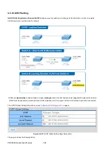
Page 122: ...vice providers carrying traffic for multiple customers across their networks QinQ tunneling is used to maintain customer specific VLAN and Layer 2 protocol configurations even when different customers...

Page 123: ...s two member ports on the switch the learning can be disabled for the particular VLAN and can therefore rely on flooding as the forwarding mechanism between the two ports This way the MAC table requir...

Page 124: ...set to All Ingress Filtering If ingress filtering is enabled checkbox is checked frames classified to a VLAN that the port is not a member of get discarded If ingress filtering is disabled frames cla...

Page 125: ...scription Port The switch port number of the logical port Interface VLAN Mode Display the current interface VLAN mode PVID Display the current PVID Accepted Frame Type Display the current access frame...

Page 126: ...rrent interface VLAN mode Membership Select VLAN membership for each interface by marking the appropriate radio button for a port or trunk Forbidden Interface is forbidden from automatically joining t...

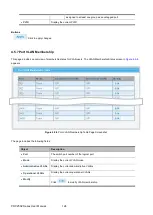
Page 127: ...r VLAN users The VLAN Membership Status screen in Figure 4 5 8 appears Figure 4 5 8 Port VLAN Membership Table Page Screenshot The page includes the following fields Object Description Port The switch...

Page 128: ...h not mandatory we suggest configuring a separate VLAN for each major protocol running on your network Do not add port members at this time 2 Create a protocol group for each of the protocols you want...

Page 129: ...urrent group ID Frame Type Display the current frame type Protocol Value Display the current protocol value Delete Click to delete the group ID entry 4 5 9 Protocol VLAN Port Setting This page allows...

Page 130: ...col VLAN group VLAN VLAN ID assigned to the Special Protocol VLAN Group Buttons Click to add protocol VLAN port entry Figure 4 5 12 Protocol VLAN Port State Page Screenshot The page includes the follo...

Page 131: ...VLANs are dynamically configured based on join messages issued by host devices and propagated throughout the network GVRP must be enabled to permit automatic VLAN registration and to support VLANs wh...

Page 132: ...ssued the applicants can rejoin before the port actually leaves the group Range 45 32760 centiseconds Default 60 centiseconds LeaveAll Timeout The interval between sending out a LeaveAll query message...

Page 133: ...ls whether GVRP is enabled or disabled on port Registration Mode By default GVRP ports are in normal registration mode These ports use GVRP join messages from neighboring switches to prune the VLANs r...

Page 134: ...t The page includes the following fields Object Description Port The switch port number of the logical port Enable Status Display the current GVRP port staste Registration Mode Display the current reg...

Page 135: ...Ports Display the current member ports Dynamic Ports Display the current dynamic ports VLAN Type Display the current VLAN type 4 5 13 GVRP Statistics The GVRP Port Statistics and Error Statistics scre...

Page 136: ...Error Statistics Page Screenshot The page includes the following fields Object Description Port The switch port number of the logical port Invaild Protocol ID Display the current invalid protocol ID I...

Page 137: ...he screen in Figure 4 5 20 appears and Table 4 5 2 describes the port configuration of the POC Managed Switches Figure 4 5 20 Two Separate VLAN Diagrams VLAN Group VID Untagged Members Tagged Members...

Page 138: ...n untagged packet Untagged packet entering VLAN 3 1 While PC 4 transmits an untagged packet enters Port 4 the switch will tag it with a VLAN Tag 3 PC 5 and PC 6 will receive the packet through Port 5...

Page 139: ...POC2502 Series User Manual 136 3 Assign Tagged Untagged to each port VLAN ID 2 Port 1 2 Untagged Port 3 Tagged Port 4 6 Excluded VLAN ID 3 Port 4 5 Untagged Port 6 Tagged Port 1 3 Excluded...

Page 140: ...Switches In most cases they are used for Uplink to other switches VLANs are separated at different switches but they need to access other switches within the same VLAN group The screen in Figure 4 5 2...

Page 141: ...Port 1 Port 2 and Port 3 VLAN Mode Hybrid PVID 2 Port 4 Port 5 and Port 6 VLAN Mode Hybrid PVID 3 Port 7 VLAN Mode Hybrid PVID 1 3 Assign Tagged Untagged to each port VLAN ID 1 Port 1 6 Untagged Port...

Page 142: ...POC2502 Series User Manual 139 VLAN ID 3 Port 4 5 Untagged Port 6 7 Tagged Port 1 3 Excluded...

Page 143: ...f a primary link failure is also accomplished automatically without operator intervention This automatic network reconfiguration provides maximum uptime to network users However the concepts of the Sp...

Page 144: ...ing higher speed links to a port that has a higher number than the current root port can cause a root port change STP Port States The BPDUs take some time to pass through a network This propagation de...

Page 145: ...STP Operation Levels The Switch allows for two levels of operation the switch level and the port level The switch level forms a spanning tree consisting of links between one or more switches The port...

Page 146: ...and a greater chance of a given port being elected as the root port 128 Port Cost A value used by STP to evaluate paths STP calculates path costs and selects the path with the minimum cost as the acti...

Page 147: ...en to forward packets 3 Illustration of STP A simple illustration of three switches connected in a loop is depicted in the below diagram In this example you can anticipate some major network problems...

Page 148: ...POC2502 Series User Manual 145 Figure 4 6 2 Before Applying the STA Rules In this example only the default STP values are used Figure 4 6 3 After Applying the STA Rules...

Page 149: ...t setting MST Instance Setting Configures each MST instance setting MST Port Setting Configures per port MST setting STP Statistics Displays the STP statistics 4 6 2 STP Global Settings This page allo...

Page 150: ...er values should be assigned to ports attached to faster media and higher values assigned to ports with slower media Force Version The STP protocol version setting Valid values are STP Compatible RSTP...

Page 151: ...includes the following fields Object Description Port Select Select port number from this drop down list External Cost 0 Auto Controls the path cost incurred by the port The Auto setting will set the...

Page 152: ...o manually re check the appropriate BPDU format RSTP or STP compatible to send on the selected interfaces Default Disabled Buttons Click to apply changes By default the system automatically detects th...

Page 153: ...Path Costs Figure 4 6 7 STP Port Status Page Screenshot The page includes the following fields Object Description Port The switch port number of the logical STP port Admin Enable Display the current...

Page 154: ...bridge Max Hops This defines the initial value of remaining Hops for MSTI information generated at the boundary of an MSTI region It defines how many bridges a root bridge can distribute its BPDU inf...

Page 155: ...Enter a value between 1 through 10 Buttons Click to apply changes Figure 4 6 9 CIST Instance Information Page Screenshot The page includes the following fields Object Description Priority Display the...

Page 156: ...n be used to control priority of ports having identical port cost See above Default 128 Range 0 240 in steps of 16 Internal Path Cost 0 Auto Controls the path cost incurred by the port The Auto settin...

Page 157: ...d root bridge External Root Cost Display the current external root cost Regional Root Bridge Display the current regional root bridge Internal Root Cost Display the current internal root cost Designat...

Page 158: ...rity Controls the bridge priority Lower numerical values have better priority The bridge priority plus the MSTI instance number concatenated with the 6 byte MAC address of the switch forms a Bridge Id...

Page 159: ...splay the current designated root bridge Internal Root Cost Display the current internal root cost Designated Bridge Display the current designated bridge Root Port Display the current root port Max A...

Page 160: ...6 15 MST Port Configuration Page Screenshot The page includes the following fields Object Description MST ID Enter the special MST ID to configure path cost and priority Port Select Select port numbe...

Page 161: ...Port ID Display the current indentifier priority port ID Internal Path Cost Conf Oper Display the current internal path cost configuration operation Regional Root Bridge Display the current regional...

Page 162: ...The switch port number of the logical STP port Configuration BPDUs Received Display the current configuration BPDUs received TCN BPDUs Received Display the current TCN BPDUs received MSTP BPDUs Recei...

Page 163: ...gures multicast throttling setting Multicast Filter Configures multicast filter 4 7 1 Properties This page provides multicast properties related configuration The multicast Properties and Information...

Page 164: ...Screenshot The page includes the following fields Object Description Unknown Multicast Action Display the current unknown multicast action status Forward Method For IPv4 Display the current IPv4 mult...

Page 165: ...they will become members of a multicast group The Internet Group Management Protocol IGMP is used to communicate this information IGMP is also used to periodically check the multicast group for membe...

Page 166: ...POC2502 Series User Manual 163 Figure 4 7 4 Multicast Flooding Figure 4 7 5 IGMP Snooping Multicast Stream Control...

Page 167: ...to keep track of the membership of multicast groups on their respective sub networks The following outlines what is communicated between a multicast router and a multicast group member using IGMP A h...

Page 168: ...affic If there is more than one router switch on the LAN performing IP multicasting one of these devices is elected querier and assumes the role of querying the LAN for group members It then propagate...

Page 169: ...t Description IGMP Snooping Status Enable or disable the IGMP snooping The default value is Disabled IGMP Snooping Version Sets the IGMP Snooping operation version Possible versions are v2 Set IGMP Sn...

Page 170: ...y number VLAN ID Display the current VLAN ID IGMP Snooping Operation Status Display the current IGMP snooping operation status Router Ports Auto Learn Display the current router ports auto learning Qu...

Page 171: ...or disable the querier state The default value is Disabled Querier Version Sets the querier version for compatibility with other devices on the network Version 2 or 3 Default 2 Buttons Click to apply...

Page 172: ...Static multicast addresses are never aged out When a multicast address is assigned to an interface in a specific VLAN the corresponding traffic can only be forwarded to ports within that VLAN The IGM...

Page 173: ...Table This page provides Multicast Database The IGMP Group Table screen in Figure 4 7 14 appears Figure 4 7 14 IGMP Group Table Page Screenshot The page includes the following fields Object Descriptio...

Page 174: ...ces within the POC Managed Switch The IGMP Router Setting and Status screens in Figure 4 7 15 Figure 4 7 16 appear Figure 4 7 15 Add Router Port Page Screenshot The page includes the following fields...

Page 175: ...he group ID entry 4 7 2 6 IGMP Router Table This page provides Router Table The Dynamic Static and Forbidden Router Table screens in Figure 4 7 17 Figure 4 7 18 Figure 4 7 19 appear Figure 4 7 17 Dyna...

Page 176: ...port mask Figure 4 7 19 Forbidden Router Table Page Screenshot The page includes the following fields Object Description VLAN ID Display the current VLAN ID Port Mask Display the current port mask 4 7...

Page 177: ...Interface is forbidden from automatically joining the IGMP via MVR None Interface is not a member of the VLAN Packets associated with this VLAN will not be transmitted by the interface Static Interfa...

Page 178: ...uery RX Special Group Query RX Display current special group query RX Special Group Source Query RX Display current special group source query RX Leave TX Display current leave TX Report TX Display cu...

Page 179: ...e includes the following fields Object Description MLD Snooping Status Enable or disable the MLD snooping The default value is Disabled MLD Snooping Version Sets the MLD Snooping operation version Pos...

Page 180: ...urrent entry number VLAN ID Display the current VLAN ID MLD Snooping Operation Status Display the current MLD snooping operation status Router Ports Auto Learn Display the current router ports auto le...

Page 181: ...from this drop down list Group IP Address The IP address for a specific multicast service Member Ports Select port number from this drop down list Buttons Click to add IGMP router port entry Figure 4...

Page 182: ...tions Life Sec Display the current life 4 7 4 4 MLD Router Setting Depending on your network connections MLD snooping may not always be able to locate the MLD querier Therefore if the MLD querier is a...

Page 183: ...rts A router port is a port on the Ethernet switch that leads towards the Layer 3 multicast device or MLD querier Forbid Port Select Specify which ports un act as router ports Buttons Click to add MLD...

Page 184: ...includes the following fields Object Description VLAN ID Display the current VLAN ID Port Display the current dynamic router ports Expiry Time Sec Display the current expiry time Figure 4 7 30 Static...

Page 185: ...shot The page includes the following fields Object Description VLAN ID Select VLAN ID from this drop down list to assign MLD membership Port The switch port number of the logical port Membership Selec...

Page 186: ...llowing fields Object Description Total RX Display the current total RX Valid RX Display the current valid RX Invalid RX Display the current invalid RX Other RX Display the current other RX Leave RX D...

Page 187: ...rent report TX General Query TX Display the current general query TX Special Group Query TX Display the current special group query TX Special Group Source Query TX Display the current special group s...

Page 188: ...et the multicast throttling number to limit the number of multicast groups an interface can join at the same time The MAX Group and Information screens in Figure 4 7 34 Figure 4 7 35 appear Figure 4 7...

Page 189: ...groups that are permitted or denied on the port A multicast filter profile can contain one or more or a range of multicast addresses but only one profile can be assigned to a port When enabled multic...

Page 190: ...nclude in the profile Specify a multicast group range by entering a start IP address Group to Specifies multicast groups to include in the profile Specify a multicast group range by entering an end IP...

Page 191: ...Click to edit parameter Click to delete the MLD IGMP profile entry 4 7 7 2 IGMP Filter Setting The Filter Setting and Status screens in Figure 4 7 38 Figure 4 7 39 appear Figure 4 7 38 Filter Setting...

Page 192: ...file entry 4 7 7 3 MLD Filter Setting The Filter Setting and Status screens in Figure 4 7 40 Figure 4 7 41 appear Figure 4 7 40 Filter Setting Page Screenshot The page includes the following fields Ob...

Page 193: ...User Manual 190 Object Description Port Display the current port Filter Profile ID Display the current filter profile ID Action Click to display detail profile parameter Click to delete the MLD filter...

Page 194: ...ecific types of traffic and preserve performance as the amount of traffic grows Reduce the need to constantly add bandwidth to the network Manage network congestion To implement QoS on your network yo...

Page 195: ...gure 4 8 2 appear Figure 4 8 1 QoS Global Setting Page Screenshot The page includes the following fields Object Description QoS Mode Enable or disable QoS mode Buttons Click to apply changes Figure 4...

Page 196: ...e page includes the following fields Object Description Port Select Select port number from this drop down list CoS Value Select CoS value from this drop down list Remark CoS Disable or enable remark...

Page 197: ...CP Remark IP Precedence Display the current remark IP precedence 4 8 2 3 Queue Settings The Queue Table and Information screens in Figure 4 8 4 Figure 4 8 5 appear Figure 4 8 4 Queue Table Page Screen...

Page 198: ...ply changes Figure 4 8 5 Queue Information Page Screenshot The page includes the following fields Object Description Information Name Display the current queue method information Information Value Dis...

Page 199: ...e from this drop down list Buttons Click to apply changes Figure 4 8 7 CoS Mapping Page Screenshot The page includes the following fields Object Description CoS Display the current CoS value Mapping t...

Page 200: ...reens in Figure 4 8 8 Figure 4 8 9 appear Figure 4 8 8 DSCP to Queue and Queue to DSCP Mapping Page Screenshot The page includes the following fields Object Description Queue Select Queue value from t...

Page 201: ...g Page Screenshot The page includes the following fields Object Description DSCP Display the current CoS value Mapping to Queue Display the current mapping to queue Queue Display the current queue val...

Page 202: ...in Figure 4 8 10 Figure 4 8 11 appear Figure 4 8 10 IP Precedence to Queue and Queue to IP Precedence Mapping Page Screenshot The page includes the following fields Object Description Queue Select Que...

Page 203: ...rrent mapping to queue Queue Display the current queue value Mapping to IP Precedence Display the current mapping to IP Precedence 4 8 3 QoS Basic Mode 4 8 3 1 Global Settings The Basic Mode Global Se...

Page 204: ...Mode Display the current QoS mode 4 8 3 2 Port Settings The QoS Port Setting and Status screens in Figure 4 8 14 Figure 4 8 15 appear Figure 4 8 14 Basic Mode Global Settings Page Screenshot The page...

Page 205: ...port number of the logical port Trust Mode Display the current trust type 4 8 4 Rate Limit Configure the switch port rate limit for the switch port on this page 4 8 4 1 Ingress Bandwidth Control This...

Page 206: ...rt rate policer The default value is Disabled Rate Kbps Configure the rate for the port policer The default value is unlimited Valid values are in the range 0 to 1000000 Buttons Click to apply changes...

Page 207: ...ndwidth Control Settings Page Screenshot The page includes the following fields Object Description Port Select port number from this drop down list State Enable or disable the port rate policer The de...

Page 208: ...Figure 4 8 20 Figure 4 8 21 appear Figure 4 8 20 Egress Queue BandwidthSettings Page Screenshot The page includes the following fields Object Description Port Select port number from this drop down l...

Page 209: ...es User Manual 206 Figure 4 8 21 Egress Queue Status Page Screenshot The page includes the following fields Object Description Queue ID Display the current queue ID Rate Limit Kbps Display the current...

Page 210: ...o Voice VLAN when relocated physically The greatest advantage of the VLAN is the equipment can be automatically placed into Voice VLAN according to its voice traffic which will be transmitted at speci...

Page 211: ...Disable Voice VLAN mode operation Voice VLAN ID Indicates the Voice VLAN ID It should be a unique VLAN ID in the system and cannot equal each port PVID It is conflict configuration if the value equal...

Page 212: ...nt voice VLAN ID Remark CoS 802 1p Display the current remark CoS 802 1p 1p Remark Display the current 1p remark Aging Display the current aging time 4 8 5 3 Telephony OUI MAC Setting Configure VOICE...

Page 213: ...digit Description User defined text that identifies the VoIP devices Buttons Click to add voice VLAN OUI setting Figure 4 8 25 Voice VLAN OUI Group Page Screenshot The page includes the following fiel...

Page 214: ...hone should configure the voice VLAN ID correctly It should be configured through its own GUI The Telephony OUI MAC Setting screens in Figure 4 8 26 Figure 4 8 27 appear Figure 4 8 26 Voice VLAN Port...

Page 215: ...2502 Series User Manual 212 The page includes the following fields Object Description Port The switch port number of the logical port State Display the current state CoS Mode Display the current CoS m...

Page 216: ...he supplicant s port number on the switch EAP is very flexible in that it allows for different authentication methods like MD5 Challenge PEAP and TLS The important thing is that the authenticator the...

Page 217: ...LAN EAPOL traffic through the port to which the client is connected After authentication is successful normal traffic can pass through the port This section includes this conceptual information Devic...

Page 218: ...es from the authentication server the server s frame header is removed leaving the EAP frame which is then encapsulated for Ethernet and sent to the client Authentication Initiation and Message Exchan...

Page 219: ...l the client initiates the authentication process by sending the EAPOL start frame When no response is received the client sends the request for a fixed number of times Because no response is received...

Page 220: ...ity 802 1X Access Control 802 1X Setting page The IEEE802 1X standard defines port based operation but non standard variants overcome security limitations as shall be explored below The 802 1X Setting...

Page 221: ...vailable No Authentication Authentication Force Authorized In this mode the switch will send one EAPOL Success frame when the port link comes up and any client on the port will be allowed network acce...

Page 222: ...iod Sets the interval for the supplicant to re transmit EAP request identify frame Maximum Request Retries The number of times that the switch transmits an EAPOL Request Identity frame without respons...

Page 223: ...in the Guest VLAN If disabled the switch will first check its history to see if an EAPOL frame has previously been received on the port this history is cleared if the port link goes down or the port s...

Page 224: ...trator defined timeout The switch follows a set of rules for entering and leaving the Guest VLAN as listed below The Guest VLAN Enabled checkbox provides a quick way to globally enable disable Guest V...

Page 225: ...e 4 9 8 Guest VLAN Status Page Screenshot The page includes the following fields Object Description Port Name The switch port number of the logical port Enable State Display the current state In Guest...

Page 226: ...e Display the current session time Authentication Method Display the current authentication method MAC Address Display the current MAC address 4 9 2 RADIUS Server This page is to configure the RADIUS...

Page 227: ...s is the period during which the switch will not send new requests to a server that has failed to respond to a previous request This will stop the switch from continually trying to contact a server th...

Page 228: ...which is unreliable by design In order to cope with lost frames the timeout interval is divided into 3 subintervals of equal length If a reply is not received within the subinterval the request is tra...

Page 229: ...t Retries Display the current retry times Priority Display the current priority Dead Time Display the current dead time Usage Type Display the current usage type Modufy Click to edit login authenticat...

Page 230: ...d Buttons Click to apply changes Figure 4 9 14 New Radius Server Page Screenshot The page includes the following fields Object Description Server Definition Set the server definition Server IP Address...

Page 231: ...wing fields Object Description IP Address Display the current IP address Port Display the current port Key Display the current key Timeout Display the current timeout Retries Display the current retry...

Page 232: ...ollowing AAA features Accounting for IEEE 802 1X authenticated users that access the network through the POC Managed Switch Accounting for users that access management interfaces on the POC Managed Sw...

Page 233: ...ame Defines a name for the authentication list Method 1 4 Set the login authentication method Empty None Local TACACS RADIUS Enable Buttons Click to add authentication list Figure 4 9 18 Login Authent...

Page 234: ...st Name Defines a name for the authentication list Method 1 3 Set the login authentication method Empty None Enable TACACS RADIUS Buttons Click to add authentication list Figure 4 9 20 Login Authentic...

Page 235: ...ge Screenshot The page includes the following fields Object Description Telnet Service Disable or enable Telnet service Login Authentication List Select login authentication list from this drop down l...

Page 236: ...re SSH on this page This page shows the Port Security status Port Security is a module with no direct configuration Configuration comes indirectly from other modules the user modules When a user modul...

Page 237: ...n Authentication List Select login authentication list from this drop down list Enable Authentication List Select enable authentication list from this drop down list Session Timeout Set the session ti...

Page 238: ...out Password Retry Count Display the current password retry count Silent Time Display the current silent time Current SSH Session Count Display the current SSH session count 4 9 5 3 HTTP The HTTP Sett...

Page 239: ...ormation Page Screenshot The page includes the following fields Object Description HTTP Service Display the current HTTP service Login Authentication List Display the current login authentication list...

Page 240: ...ble HTTPs service Login Authentication List Select login authentication list from this drop down list Session Timeout Set the session timeout value Buttons Click to apply changes Figure 4 9 28 HTTPs I...

Page 241: ...Priority 1 65535 Set priority The allowed value is from 1 to 65535 Management Method Indicates the host can access the switch from HTTP HTTPs telnet SSH SNMP All interface that the host IP address mat...

Page 242: ...he current source IPv4 address Source IPv4 Mask Display the current source IPv4 mask Source IPv6 Display the current source IPv6 address Source IPv6 Prefix Display the current source IPv6 prefix Modif...

Page 243: ...40 Click to apply changes Figure 4 9 32 Access Profile Table Page Screenshot The page includes the following fields Object Description Access Profile Display the current access profile Delete Click to...

Page 244: ...snooping is used to filter DHCP messages received on a non secure interface from outside the network or firewall When DHCP snooping is enabled globally and enabled on a VLAN interface DHCP messages re...

Page 245: ...ernet header If the DHCP packet is not a recognizable type it is dropped If a DHCP packet from a client passes the filtering criteria above it will only be forwarded to trusted ports in the same VLAN...

Page 246: ...tion Page Screenshot The page includes the following fields Object Description DHCP Snooping Display the current DHCP snooping status 4 9 7 3 VLAN Setting Command Usage When DHCP snooping is enabled g...

Page 247: ...de operation Possible modes are Enabled Enable DHCP snooping mode operation When DHCP snooping mode operation is enabled the request DHCP messages will be forwarded to trusted ports and only allowed r...

Page 248: ...this port are removed Set all ports connected to DHCP servers within the local network or firewall to trusted state Set all other ports outside the local network or firewall to untrusted state The DH...

Page 249: ...des the following fields Object Description Port The switch port number of the logical port Type Display the current type Chaddr Check Display the current chaddr check 4 9 7 5 Statistics The DHCP Snoo...

Page 250: ...ace belongs A checksum value the end of each entry is the number of bytes from the start of the file to end of the entry Each entry is 72 bytes followed by a space and then the checksum value To keep...

Page 251: ...ing fields Object Description Database Type Select database type File Name The name of file image Remote Server Fill in your remote server IP address Write Delay Specify the duration for which the tra...

Page 252: ...Server Display the current remote server Write Delay Display the current write delay Timeout Display the current timeout 4 9 7 7 Rate Limit After enabling DHCP snooping the switch will monitor all th...

Page 253: ...te limit for the port policer The default value is unlimited Valid values are in the range 1 to 300 Buttons Click to apply changes Figure 4 9 43 DHCP Rate Limit Setting Page Screenshot The page includ...

Page 254: ...s Circuit ID option 1 Remote ID option 2 The Circuit ID sub option is supposed to include information specific to which circuit the request came in on The Remote ID sub option was designed to carry in...

Page 255: ...contains option 82 The drop mode means that if the message has option 82 then the system will drop it without processing keep mode means that the system will keep the original option 82 segment in th...

Page 256: ...ect modes from this drop down list The following modes are available Drop Keep Replace Buttons Click to apply changes Figure 4 9 47 Option 82 Global Setting Page Screenshot The page includes the follo...

Page 257: ...Screenshot The page includes the following fields Object Description Port Select port for this drop down list VLAN Indicates the ID of this particular VLAN Circuit ID Set the option1 Circuit ID conte...

Page 258: ...tion related configuration A Dynamic ARP prevents the untrusted ARP packets based on the DHCP Snooping Database 4 9 8 1 Global Setting DAI Setting and Information screens in Figure 4 9 50 Figure 4 9 5...

Page 259: ...he following fields Object Description VLAN ID Indicates the ID of this particular VLAN Status Enables Dynamic ARP Inspection on the specified VLAN Options Enable Disable Buttons Click to apply change...

Page 260: ...urce MAC address in the Ethernet header against the sender MAC address in the ARP body This check is performed on both ARP requests and responses When enabled packets with different MAC addresses are...

Page 261: ...he following fields Object Description Port The switch port number of the logical port Type Display the current port type Src Mac Chk Display the current Src Mac Chk status Dst Mac Chk Display the cur...

Page 262: ...The switch port number of the logical port Forwarded Display the current forwarded Source MAC Failures Display the current source MAC failures Dest MAC Failures Display the current source MAC failures...

Page 263: ...s Object Description Port Select port from this drop down list State Set default or user define Rate Limit pps Configure the rate limit for the port policer The default value is unlimited Buttons Clic...

Page 264: ...n a host tries to spoof and use the IP address of another host After receiving a packet the port looks up the key attributes including IP address MAC address and VLAN tag of the packet in the binding...

Page 265: ...P Source Guard Port Setting Page Screenshot The page includes the following fields Object Description Port Select port from this drop down list Status Enable or disable the IP source guard Verify Sour...

Page 266: ...tus Display the current status Verify Source Display the current verify source Max Binding Entry Display the current max binding entry Current Binding Entry Display the current binding entry 4 9 9 2 B...

Page 267: ...add authentication list Figure 4 9 63 IP Source Guard Binding Table Status Page Screenshot The page includes the following fields Object Description Port Display the current port VLAN ID Display the...

Page 268: ...ort Security Setting Page Screenshot The page includes the following fields Object Description Port Select port from this drop down list Security Enable or disable the port security Mac L2 Entry The m...

Page 269: ...If Limit 1 MAC addresses is seen on the port it will trigger the action that do not learn the new MAC and drop the package Buttons Click to apply changes Figure 4 9 65 Port Security Status Page Screen...

Page 270: ...k of sensitive data of the server Security feature refers to applications such as protocol check which is for protecting the server from attacks such as DoS The protocol check allows the user to drop...

Page 271: ...ption DMAC SMAC Enable or disable DoS check mode by DMAC SMAC Land Enable or disable DoS check mode by land UDP Blat Enable or disable DoS check mode by UDP blat TCP Blat Enable or disable DoS check m...

Page 272: ...check mode by TCP min hdr size TCP SYN SPORT 1024 Enable or disable DoS check mode by TCP syn sport 1024 Null Scan Attack Enable or disable DoS check mode by null scan attack X Mas Scan Attack Enable...

Page 273: ...ze status Smurf Attack Display the current smurf attack status TCP Min Header Length Display the current TCP min header length TCP SYN SPORT 1024 Display the current TCP syn status Null Scan Attack Di...

Page 274: ...ection Enable or disable per port DoS protection Buttons Click to apply changes Figure 4 9 68 Port Security Setting Page Screenshot The page includes the following fields Object Description Port The s...

Page 275: ...obal Setting and Information screens in Figure 4 9 69 Figure 4 9 70 appear Figure 4 9 69 Storm Control Global Setting Page Screenshot The page includes the following fields Object Description Unit Con...

Page 276: ...tion screens in Figure 4 9 71 Figure 4 9 72 appear Figure 4 9 71 Storm Control Setting Page Screenshot The page includes the following fields Object Description Port Select port for this drop down lis...

Page 277: ...ption Port The switch port number of the logical port Port State Display the current port state Broadcast Kbps pps Display the current broadcast storm control rate Unknown Multicast Kbps pps Display t...

Page 278: ...D There are three ACE frame types Ethernet Type ARP and IPv4 and two ACE actions permit and deny The ACE also contains many detailed different parameter options that are available for individual appli...

Page 279: ...Delete Click to delete ACL name entry 4 10 2 MAC based ACE An ACE consists of several parameters Different parameter options are displayed depending on the frame type that you select The MAC based ACE...

Page 280: ...e DA MAC address 1 ARP frames where SHA is equal to the DA MAC address SA MAC Specify the source MAC filter for this ACE Any No SA MAC filter is specified User Defined If you want to filter a specific...

Page 281: ...Display the current destination MAC address Destination MAC Address Mask Display the current destination MAC address mask Source MAC Address Display the current source MAC address Source MAC Address...

Page 282: ...Pv4 based ACL Page Screenshot The page includes the following fields Object Description ACL Name Create a name from IPv4 based ACL list Buttons Click to add ACL name list Figure 4 10 6 ACL Table Page...

Page 283: ...POC2502 Series User Manual 280 Figure 4 10 7 IP based ACE Page Screenshot...

Page 284: ...address The legal format is xxx xxx xxx xxx A frame that hits this ACE matches this source IP address value Source IP Wildcard Mask When User Defined is selected for the source IP filter you can enter...

Page 285: ...TCP Urgent Pointer field significant URG value for this ACE Set TCP frames where the URG field is set must be able to match this entry Unset TCP frames where the URG field is set must not be able to m...

Page 286: ...a specific IP recedence with this ACE you can enter a specific IP recedence value A field for entering an IP recedence value appears The allowed range is 0 to 7 A frame that hits this ACE matches this...

Page 287: ...sk Display the current destination IP address wildcard mask Source Port Range Display the current source port range Destiantion Port Range Display the current destination port range Flag Set Display t...

Page 288: ...Buttons Click to add ACL name list Figure 4 10 10 ACL Table Page Screenshot The page includes the following fields Object Description Delete Click to delete ACL name entry 4 10 6 IPv6 based ACE An AC...

Page 289: ...POC2502 Series User Manual 286 Figure 4 10 11 IP based ACE Page Screenshot The page includes the following fields...

Page 290: ...h When User Defined is selected for the source IP filter you can enter a specific SIP prefix length in dotted decimal notation Destination IP Address Specify the Destination IP address filter for this...

Page 291: ...URG value for this ACE Set TCP frames where the URG field is set must be able to match this entry Unset TCP frames where the URG field is set must not be able to match this entry Don t Care Any value...

Page 292: ...r a specific IP recedence with this ACE you can enter a specific IP recedence value A field for entering a IP recedence value appears The allowed range is 0 to 7 A frame that hits this ACE matches thi...

Page 293: ...destination IP address Destination IP Address Wildcard Mask Display the current destination IP address wildcard mask Source Port Range Display the current source port range Destination Port Range Disp...

Page 294: ...llowing fields Object Description Port The switch port number of the logical port MAC ACL Display the current MAC ACL IPv4 ACL Display the current IPv4 ACL IPv6 ACL Display the current IPv6 ACL Modify...

Page 295: ...e removed from the MAC table if no frame with the corresponding SMAC address has been seen after a configurable age time 4 11 1 Static MAC Setting The static entries in the MAC table are shown in this...

Page 296: ...y 4 11 2 MAC Filtering By filtering MAC address the switch can easily filter the per configured MAC address and reduce the un safety The Static MAC Setting screens in Figure 4 11 3 Figure 4 11 4 appea...

Page 297: ...lete static MAC status entry 4 11 3 Dynamic Address Setting By default dynamic entries are removed from the MAC table after 300 seconds The Dynamic Address Setting Status screens in Figure 4 11 5 Figu...

Page 298: ...The MAC Table is sorted first by VLAN ID then by MAC address The Dynamic Learned screens in Figure 4 11 6 Figure 4 11 7 appear Figure 4 11 6 Dynamic Learned Page Screenshot The page includes the follo...

Page 299: ...nformation Page Screenshot Object Description MAC Address The MAC address of the entry VLAN The VLAN ID of the entry Type Indicates whether the entry is a static or dynamic entry Port The ports that a...

Page 300: ...point Discovery LLDP MED is an extension of LLDP intended for managing endpoint devices such as Voice over IP phones and network switches The LLDP MED TLVs advertise information such as network policy...

Page 301: ...n a port is disabled LLDP is disabled or the switch is rebooted a LLDP shutdown frame is transmitted to the neighboring units signaling that the LLDP information isn t valid anymore TX Reinit controls...

Page 302: ...DP status LLDP PDU Disable Action Display the current LLDP PDU disable action Transmission Interval Display the current transmission interval Holdtime Multiplier Display the current holdtime multiplie...

Page 303: ...ort from this drop down list State Enables LLDP messages transmit and receive modes for LLDP Protocol Data Units Options TX only RX only Tx RX Disabled Port Select Select port from this drop down list...

Page 304: ...d in LLDP information transmitted Management Address When checked the Management Address is included in LLDP information transmitted 802 1 PVID When checked the 802 1 PVID is included in LLDP informat...

Page 305: ...he page includes the following fields Object Description Port Select Select port from this drop down list VLAN Select Select VLAN from this drop down list Buttons Click to apply changes Figure 4 12 6...

Page 306: ...appear Figure 4 12 7 Local Device Summary Page Screenshot The page includes the following fields Object Description Chassis ID Subtype Display the current chassis ID subtype Chassis ID Display the cu...

Page 307: ...rt LLDP Status Display the current LLDP status LLDP MED Status Display the current LLDP MED Status 4 12 5 LLDP Remote Device This page provides a status overview for all LLDP remote devices The displa...

Page 308: ...is ID The Chassis ID is the identification of the neighbor s LLDP frames Port ID Subtype Display the current port ID subtype Port ID The Remote Port ID is the identification of the neighbor port Syste...

Page 309: ...of application types supported on a given port The application types specifically addressed are 1 Voice 2 Guest Voice 3 Softphone Voice 4 Video Conferencing 5 Streaming Video 6 Control Signaling cond...

Page 310: ...hanced security by isolation from data applications Voice Signaling for use in network topologies that require a different policy for the voice signaling than for the voice media This application type...

Page 311: ...rtised in the Video Conferencing application policy VLAN ID VLAN identifier VID for the port as defined in IEEE 802 1Q 2003 Tag Tag indicating whether the specified application type is using a tagged...

Page 312: ...ication Display the current application VLAN ID Display the current VLAN ID VLAN Tag Display the current VLAN tag status L2 Priertity Display the current L2 prierity DSCP Value Dusplay the current DSC...

Page 313: ...esult in voice quality degradation or complete service disruption Location This option advertises location identification details Inventory This option advertises device details useful for inventory m...

Page 314: ...ollowing fields Object Description Port Select port from this drop down list Location Coordinate A string identifying the Location Coordinate that this entry should belong to Location Civic Address A...

Page 315: ...he LLDP Port Overloading screen in Figure 4 12 16 appears Figure 4 12 16 LLDP Port Overloading Table Page Screenshot The page includes the following fields Object Description Interface The switch port...

Page 316: ...ry Displays if the mandatory group of TLVs was transmitted or overloaded 802 1 TLVs Displays if the 802 1 TLVs were transmitted or overloaded 4 12 9 LLDP Statistics Use the LLDP Device Statistics scre...

Page 317: ...andard LLDP frames require a new entry in the table when the Chassis ID or Remote Port ID is not already contained within the table Entries are removed from the table when a given port links down an L...

Page 318: ...s have the ability to identify the cable length and operating conditions and to isolate a variety of common faults that can occur on the Cat5 twisted pair cabling There might be two statuses as follow...

Page 319: ...ds Object Description Port Select port from this drop down list Buttons Click to run the diagnostics Figure 4 13 2 Test Results Page Screenshot The page includes the following fields Object Descriptio...

Page 320: ...s are transmitted and the sequence number and roundtrip time are displayed upon reception of a reply The page refreshes automatically until responses to all packets are received or until a timeout occ...

Page 321: ...trip time are displayed upon reception of a reply The page refreshes automatically until responses to all packets are received or until a timeout occurs The ICMPv6 Ping screen in Figure 4 13 4 appears...

Page 322: ...ket with TTL at 2 will be sent Also the send hop may be a TTL timeout return but the procedure will carries on till the data packet is sent to its destination These procedures is for recording every s...

Page 323: ...d by the Agent History Record periodical statistic samples available from Statistics Alarm Allow management console users to set any count or integer for sample intervals and alert thresholds for RMON...

Page 324: ...al number of packets received that were longer than 1518 octets Fragements The number of frames which size is less than 64 octets received with invalid CRC Jabbers The number of frames which size is l...

Page 325: ...sible types are none The total number of octets received on the interface including framing characters log The number of uni cast packets delivered to a higher layer protocol SNMP Trap The number of b...

Page 326: ...ription Last Sent Time Display the current last sent time Owner Display the current event owner Action Click to delete RMON event entry 4 14 3 RMON Event Log This page provides an overview of RMON Eve...

Page 327: ...rom this drop down list Sample Variable Indicates the particular variable to be sampled the possible variables are DropEvents The total number of events in which packets were dropped due to lack of re...

Page 328: ...FCS octets Pkts64to172Octets The total number of frames including bad packets received andtransmitted where the number of octets fall within the specified range excluding framing bits but including FC...

Page 329: ...ON Alarm Status Page Screenshot The page includes the following fields Object Description Index Indicates the index of Alarm control entry Sample Port Display the current sample port Sample Variable D...

Page 330: ...ndex Index Indicates the index of the history entry Sample Port Select port from this drop down list Bucket Requested Indicates the maximum data entries associated this History control entry stored in...

Page 331: ...e current interval Owner Display the current owner Action Click to delete RMON history entry 4 14 6 RMON History Log This page provides a detail of RMON history entries screen in Figure 4 14 9 appears...

Page 332: ...amera system and AP group for the enterprise Without the power socket limitation the POC Managed Switch makes the installation of cameras or WLAN APs easier and more efficient PoE Power Budget list fo...

Page 333: ...reless AP and any 802 3af at complied powered device PD Approved IFS Long Reach PoE Extenders The following list of approved IFS Long Reach PoE extenders is correct at the time of publication Long Rea...

Page 334: ...gregated power of the system is lower than the power level at which additional PDs cannot be connected When this value is exceeded ports will be deactivated according to user defined priorities The po...

Page 335: ...e PoE power to PD Temperature Threshold Allows setting over temperature protection threshold value If the system temperature is overly high the system will lower the total PoE power budget automatical...

Page 336: ...port with the lowest priority will be turned off and offer power for the port of higher priority Current Used mA The Power Used shows how much current the PD currently is using Power Used W The Power...

Page 337: ...mental protection on the Earth the Managed PoE switch can effectively control the power supply besides its capability of giving high watts power The PoE schedule function helps you to enable or disabl...

Page 338: ...port PoE Mode option to enable you to indicate which schedule profile could be applied to the PoE port The page includes the following fields Object Description Profile Set the schedule profile mode...

Page 339: ...function offers administrator to reboot PoE device at an indicated time if administrator has this kind of requirement Reboot Only Allows user to reboot PoE function by PoE reboot schedule Please note...

Page 340: ...nce the PD stops working and without response the PoE Switch is going to restart PoE port port power and bring the PD back to work It will greatly enhance the reliability and reduces administrator man...

Page 341: ...the PoE port will be reset Action Allows user to set which action will be applied if the PD is without any response The POC2502 PoC Switch offers the following 3 actions PD Reboot It means system will...

Page 342: ...the IP configuration is retained The new configuration is available immediately which means that no restart is necessary The Factory Default screen in Figure 4 15 1 appears and click to reset the con...

Page 343: ...rent image or configuration of the POC Managed Switch to the local management station The Backup Manager screen in Figure 4 16 3 appears Figure 4 16 3 Backup Manager Page Screenshot The page includes...

Page 344: ...in Figure 4 16 4 appears Figure 4 16 4 Upgrade Manager Page Screenshot The page includes the following fields Object Description Upgrade Method Select upgrade method from this drop down list Server IP...

Page 345: ...reens in Figure 4 16 5 Figure 4 16 6 appear Figure 4 15 5 Dual Image Configuration Page Screenshot The page includes the following fields Object Description Active Image Select the active or backup im...

Page 346: ...packet then this packet will be filtered thereby increasing the network throughput and availability 5 4 Store and Forward Store and Forward is one type of packet forwarding techniques A Store and For...

Page 347: ...POC2502 Series User Manual 344 No packet loss will occur...

Page 348: ...ower On or Reset This is done by detecting the modes and speeds when both devices are connected Both 10BASE T and 100BASE TX devices can connect with the port in either half or full duplex mode If att...

Page 349: ...will be poor Please also check the in out rate of the port Why the Switch doesn t connect to the network Solution 1 Check the LNK ACT LED on the POC Managed Switch 2 Try another port on the POC Manag...

Page 350: ...POC2502 Series User Manual 347 4 If that device works refer to the next step 5 If that device does not work check the AC power...

Page 351: ...10 100Mbps Ethernet Switch to another switch a bridge or a hub a straight or crossover cable is necessary Each port of the Switch supports auto MDI MDI X detection That means you can directly connect...

Page 352: ...ue 6 Green 7 White Brown 8 Brown 1 White Orange 2 Orange 3 White Green 4 Blue 5 White Blue 6 Green 7 White Brown 8 Brown SIDE 2 Crossover Cable SIDE 1 SIDE 2 1 2 3 4 5 6 7 8 1 2 3 4 5 6 7 8 SIDE 1 1 W...

Reviews: