background image

20

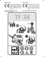
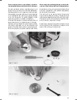
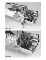
• Poner en funcionamiento el aparato y, en caso 

necesario, elevar el paso de gasolina, girando 
la aguja dosificadora (17) hacia la izquierda (1/2 
vuelta) (véase ilustr. 4)

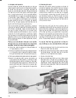
• Después de la fase de calentamiento, observar 

con gafas protectoras la llama en el interior del 
resonador (97) a una distancia prudente de aprox. 
2 m. La llama no debe salir del resonador. De 
ser así, girar la aguja dosificadora (17) hacia la 
derecha para reducir el paso de gasolina y luego 
volver a controlar la llama.

• ”Inundación”: Al arrancar el aparato caliente pu-

ede inundarse el carburador debido a un bombeo 
demasiado violento. En este caso saldrán gases 
de gasolina por el extremo del tubo nebulizador 
(108). Presionar el botón de parada (52) a la 
posición STOP, pulsar el botón de arranque (78) 
y accionar la bomba de aire hasta que ya no se 
oigan explosiones. Después arrancar como se 
costumbre pero sin bombear demasiado.

C) El aparato no arranca
Si el aparato no arranca, se deben considerar 
los siquientes pasos:
• controlar el contenido del tanque de gasolina
• controlar el encendido:
Presionar el botón de arranque (78). Se debe oír 
un zumbido. De no ser así: 
1)  Comprobar la posición correcta de las pilas y 

el voltaje de la mismas. Comprobe el voltio de 
las pilas (pròxi, se tienen que medir 6 voltios) 
Si el voltaje no es correcto, cambiar las pilas. 
Después pulsar el botón de arranque, se deberia 
oír el zumbido. Siga de la forma siquiente:

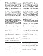
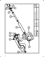
2)  Quitar el enchufe para bujía (104) del cuerpo 

de desplazamiento (26) y sacar el cuerpo de 
desplazamiento de cámara de mezcla después 
de haber destornillado los tornillos (36). Limpiarlo 
con cepillo (145/8) por si acaso habrá residuos o 
con aire de presión. Volver a poner con ciudado 
el cuerpo de desplazamiento en la cámara de 
mezcla. Apretar los tornillos y volver a sobrepo-
ner el enchufe para bujía (104). Pulsar el botón 
de arranque (78). Si todavia no hay zumbido. 
Siga de la forma siquiente:

3)  Comprobar si el muelle de contacto (87), los 

tornillos mariposa (88) y el soporte (84) están bien 
conectados unos con otros. Si hay suciedades 
en las superficies de contacto, limpiarlas.

4)  Reemplazar la bobina de encendido (79) y el 

cable de encendido (79/1).

• Comprobar la tapa (8) y la junta (9) del tanque de 

gasolina (10). Verificar si hay daños en el borde 
del racor roscado.

• Extraer la aguja dosificadora (17), accionar la 

bomba (91). Deberá salir gasolina. De no ser asi:

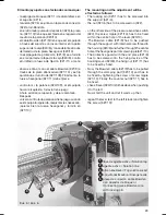
• Start unit and, if necessary, increase the petrol 

flow rate by adjusting the regulating needle (17) 
with the screw driver (145/1) approx. 1/2 turn to 
the left counter clockwise (illus. 4).

• After warming-up period look into the resonator 

(97) at a safe distance (approx. 2 m) with safety 
eye glasses and check flame. The flame should 
not come out of the resonator (97). Should this 
be the case, reduce petrol flow by turning the 
regulating needle (17) clockwise to the right and 
then re-check the flame.

• “Flooding”: When starting the warm unit, it is pos-

sible due to vigorous pumping that the carburettor 
floods. In this case, petrol fumes emerge at the 
end of the fog tube (108). Push down the stop 
button (52) to STOP position, press the starter 
button (78) and actuate pump spindle (91) until 
no more explosions are audible. Then restart as 
normal but do not pump too vigorously.

C) Unit does not start
If the unit does not start, the following steps should 
be considered:
• Check fuel tank whether petrol supply is sufficient
• Check ignition:
Press starter button (78). A buzzer sound must be 
audible. If not, proceed as follows:
1)  Check battery position (plus side must point into 

the unit). Check voltage of batteries (approx. 6 
Volts must be measured). If voltage is not correct, 
replace batteries. Then press starter button (78) 
again. A buzzer sound must be audible. If not, 
proceed as follows:

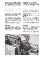
2)  Remove spark plug socket (104) from swirl vane 

(26). After having unscrewed the 2 screws (36), 
pull the swirl vane out of mixing chamber (23) 
and clean the swirl vane with brush (145/8) and 
by means of compressed air. Put swirl vane 
carefully into the mixing chamber (23) and fix 
with screws (36). Press spark plug socket ((104) 
onto the swirl vane. Press starter button (78). A 
buzzer sound must be audible. If not, proceed 
as follows:

3)  Check whether the contact spring (87), the 

wing  screw (88) and the support (84) are well 
connected with each other. Clean the contact 
surfaces, if contact surfaces are covered with 
dirt or rust.

4)  Replace ignition coil (79) and ignition cable 

(79/1).

• Check cap (8) and gasket (9) of fuel tank (10). 

Check edge of screwneck for damage.

• Unscrew regulating needle (17), actuate air pump 

(91), petrol should emerge.

Summary of Contents for TF 34

Page 1: ...1 Nebulizador Fog Generator Instrucciones de funcionamiento Instruction Manual TF 34...

Page 2: ...for the purchase of our IGEBA quality product and we wish you every success in the employment of this equipment For a better understanding of the Instruction Manual parts of the unit described in the...

Page 3: ...r an est n fuera de la responsibilidad de IGEBA Restricted fields of application The units TF 34 TF 34E are suitable for transforming chemical solutions formulations into finest aerosol fog The units...

Page 4: ...ar la cantidad de paso del agente activo Solution output through dosage nozzles 15 Activador agente y aditivos Formulations and fogging additives 16 2 Arrancar el aparato y nebulizar 2 Starting the un...

Page 5: ...n qu mica sin correr peligrodequesedescompongandebidoatiempos de espera extremadamente cortos en el chorro de gas La alta temperatura del gas provoca el efecto pticodeunanieblavisible debidoaevaporiz...

Page 6: ...omagn tica 2004 108 EG Electromagnetic compatibility 2004 108 EG que los siguientes productos han sido fabricados de conformidad con las directivas CE arriba indicadas the following product line is pr...

Page 7: ...ones 3 Deber n seguirse las recomendaciones de dosificaci n de los fabricantes de los medios Attention 1 The operation of these units has to be made only by well instructed people 2 The fogging of fla...

Page 8: ...face Bater as desgastadas se tienen que eliminar aparte Nunca su ministre bater as viejas y partes electr nicas a la basura Hand in old batteries at collection point Never dispose old batteries and el...

Page 9: ...n sumini strada cumple todos los requisitos delasdirectivasdelaCE2004 108 CEE Compatibilidad electromag n tica y 2006 42 EG la directriz maquenaria CE marking The shipped version of this device compl...

Page 10: ...nebulizaci n 9 No se permite transportar el equipo en veh cu los cerrados mientras est a n caliente Esperen hasta que se haya enfriado hasta la temparatura ambiente Read Safety Instructions Before fi...

Page 11: ...aparato no funciona perfectamente 19 No nebulicen directamente contra paredes personas y otros objetos Mantengan una distan cia m nima de por lo menos 3 metros quando el aparato esta en marcha 10 Nev...

Page 12: ...transporte y almacenamiento 30 Peligro de quemaduras Peligro de encendio a tropezar 31 Dirreci n recorrida afrontado al hacer niebla Hay que cuidar bastante vista 20 If the unit stops running due to m...

Page 13: ...ings or leaned on hot parts of the running or cooled unit Otrasmanipulacionesnopermitidasymodifica ci ndelaparatofueradelasdirectricesoficiales No est permitido realizar modificaci nes en el aparato s...

Page 14: ...14 Illus 3 illus 3 Illus 4 illus 4...

Page 15: ...illa Quando se cambia la boquilla 117 a atornillar y desatornillas se tiene que usar incondicional una segundallavereplicandoelelpalmedeniebla 114 1 How to prepare unit ready for use After removing th...

Page 16: ...umen de producto en relaci n al espacio 10 soluci n 0 05 l 100 m3 Instrucciones del fabricante respecto a mezcla de producto 0 5 litros 10 soluci n 9 5 litros de aditivo Ej Gasoil 10 litros producto F...

Page 17: ...es presionar el mismo tiempo el bot n de arranque 78 Explosiones de los gases restantes se podrian o r Decomprimir el tanque de agente activo girando la tapa de tanque 2 en sentido horario Atenci n Cu...

Page 18: ...olar si est da ada pliegues o da os similares y limpiarla Limpiar igualmente la placa de v vula 34 y la placa perforada 32 Para ello se puede usar por ejemplo un trapo impregnado de gasolina ilustr 2...

Page 19: ...be tener presente que nuestra f brica se encuentra a aprox 800 m sobre el nivel del mar y que la temperatura media de la nave de ensayos es de approx 15 Esto significa que es necesario reajustar el ap...

Page 20: ...la tapa 8 y la junta 9 del tanque de gasolina 10 Verificar si hay da os en el borde del racor roscado Extraer la aguja dosificadora 17 accionar la bomba 91 Deber salir gasolina De no ser asi Start un...

Page 21: ...ficadoradeagenteactivo 117 respectivamente el taladora de la boquilla Controlar si est obstruido el pit n nebulizador 114 Extraer la v lvula de presi n 38 de la c mara de mezcla 23 y controlar si la m...

Page 22: ...l aparato resp el resonador 97 estandocaliente Estoseexplicapor el hecho que el pit n nebulizador 114 cambia su posici n de unos 15mm aprox Hacia la izquierda debido a la extensi n t rmica del resonad...

Page 23: ...The mounting and the adjustment will be effected as follows The locking pin 321 1 has to be screwed into the support 321 4 the nut 321 6 has to be screwed on 322 on the other side at the pressure sen...

Page 24: ...OGGING with emergency cut off E Preparetheunitinthenormalwayandstart open solution tap 120 lever downwards illus 6 No fog will emit Fog will be visible only when lever 320 10 of the emergency cut off...

Page 25: ...34 model E with emergency cut off device pieza de conexi n cable Bowden con pasador de bloqueo Connecting piece Bowdenwire with locking pin corte emergencia Emergency cut off device 34 Manual de inst...

Page 26: ...L 27 x 34 x 78 cm Standard accessories TF 34 1 Set of flow control nozzles 08 10 l h 10 15 l h 1 Fuel funnel with strainer mesh 0 2 mm X 1 Solution funnel with strainer mesh 0 2 mm X 1 Tool bag X 1 P...

Page 27: ...1 2 2 3 3 4 4 5 5 6 6 A B C D Ersatzteilzeichnung Part drawing Pi ces de rechange Piezas de recambio 1 Seite Page P gina 12 05 2011 IGEBA IGEBA Geraetebau GmbH 87480 Weitnau Germany Typ Type El tipo...

Page 28: ...Seite Page P gina 28 04 2011 IGEBA IGEBA Geraetebau GmbH 87480 Weitnau Germany Typ Type El tipo Ausgabe 110 65 107 62 74 65 84 74 98 62 65 73 65 80 85 82 66 65 67 65 67 TF34 11 2014 Rahmen mit Befest...

Page 29: ...M5x10 VA 6 74 Grommet Manguito de goma 10 06 000 05 1 80 Label Series of Batteries Placa posicionamiento de las pilas 10 00 000 09 1 82 Support Soporte 10 00 100 00 1 84 Support Soporte 10 00 200 00...

Page 30: ...Page P gina 12 05 2011 IGEBA IGEBA Geraetebau GmbH 87480 Weitnau Germany Typ Type El tipo Ausgabe 86 86 1 87 79 104 79 1 79 2 76 65 73 72 71 74 71 71 1 88 78 77 TF34 02 2016 10 06 000 00 Batteriestart...

Page 31: ...a DIN 1587 M4 2 77 Starter button Bot n de arranque 10 06 000 04 1 78 Ignition coil with cable an grommet Bobina de encendido 10 06 300 00 1 79 Spark plug cable Cable de encendido 10 06 300 02 1 79 1...

Page 32: ...zas de recambio Seite Page P gina 28 04 2011 IGEBA IGEBA Geraetebau GmbH 87480 Weitnau Germany Typ Type El tipo Ausgabe 155 3 4 5 158 119 118 9 8 1 2 7 TF34 5 2011 6 01 000 00 6 Wirkstoffbeh lter Solu...

Page 33: ...1 7 Cap Tapa 10 02 200 01 1 8 Gasket Junta 10 02 200 02 1 9 Gasket Junta de cobre DIN 7603 A10x13 5 Cu 1 118 Spacer for rising line Pieza intermedia para conducto de ascensi n 8 01 100 01 1 119 Label...

Page 34: ...de rechange Piezas de recambio Seite Page P gina 27 04 2011 IGEBA IGEBA Geraetebau GmbH 87480 Weitnau Germany Typ Type El tipo Ausgabe TF34 6 02 000 00 5 2011 10 1 162 8 9 160 10 156 7 8 Benzintank Ga...

Page 35: ...te 6 02 000 01 1 10 1 Rating plate Placa de identificaci n 10 00 000 10 1 156 label Fuel tank capacity Placa Capacidad tanque de gasolina 8 02 000 01 1 160 Sign IGEBA 88x25mm Placa IGEBA 88x25mm 10 00...

Page 36: ...recambio Seite Page P gina 29 04 2011 IGEBA IGEBA Geraetebau GmbH 87480 Weitnau Germany Typ Type El tipo Ausgabe 113 108 114 100 97 100 1 102 1 101 1 101 1 102 1 103 65 102 101 105 Seite 12 Page 12 P...

Page 37: ...ador 6 05 200 03 2 101 1 Shell with cutout Cubre resonador izquierdo 6 05 240 00 1 102 Clamp Uni n cubre resonador 6 05 200 04 2 102 1 Hood Tapa resonador 6 05 220 00 1 103 Tapping screw Tornillo de c...

Page 38: ...au GmbH 87480 Weitnau Germany Typ Type El tipo Ausgabe 37 39 42 40 41 43 35 44 46 47 36 130 12 13 56 55 57 15 58 59 26 36 17 18 14 61 60 60 1 73 36 34 33 32 63 28 23 27 27 22 20 21 52 51 50 18 106 106...

Page 39: ...ket Anillo de obturaci n DIN 7603 A10 x 13 Vf 2 37 Valve cpl V lvula completa 10 00 700 00 2 38 Valve V lvula 10 00 700 01 2 39 Diaphragm Membrana 10 00 700 02 2 40 O Ring Anillo de junta O Ring 5x1 5...

Page 40: ...1 IGEBA IGEBA Geraetebau GmbH 87480 Weitnau Germany Typ Type El tipo Ausgabe 116 118 117 127 37 133 132 37 127 37 130 137 37 139 43 134 2 134 1 128 124 122 129 1 129 123 126 125 131 120 134 TF34 5 201...

Page 41: ...cero fino DIN 966 M4x10 VA 1 128 Disk spring stainless steel Resorte de platillo acero fino DIN 2093 B20x10 2x0 8 4 129 Spacer disk stainless steel anillo de distancia acero fino DIN 988 10x16x0 3 VA...

Page 42: ...p Tapa de bomba 8 04 120 01 1 92 Spring Muelle 8 04 120 02 1 93 Pump spindle Barra de bomba 8 04 120 03 1 94 Collar Collar 10 04 120 04 1 95 Handle Mango 10 04 120 05 1 96 1 1 2 2 3 3 4 4 5 5 6 6 A A...

Page 43: ...proteccion TF W34 6 00 905 00 1 352 Gasket Junta de cobre DIN 7603 A10x13 5 Cu 2 353 Dosage nozzle 0 6 Boquilla dosificadora 0 6 11 07 004 00 1 354 Ersatzteilzeichnung Part drawing Pi ces de rechange...

Page 44: ...as de recambio Seite Page P gina 12 05 2011 IGEBA IGEBA Geraetebau GmbH 87480 Weitnau Germany Typ Type El tipo Ausgabe 143 145 6 145 5 145 1 145 3 145 8 145 4 145 2 145 9 145 141 141 1 142 142 1 6 10...

Page 45: ...1 145 1 Carrying strap Correa portadora 10 00 000 27 1 145 2 Pipe cleaning tool Limpiatubos 10 00 000 20 1 145 3 Screw driver Destornillador 10 00 000 24 1 145 4 Double open ended spanner Llave de dos...

Page 46: ...Type El tipo Ausgabe 137 118 322 321 2 321 3 321 1 321 4 321 5 321 6 321 7 321 8 321 9 320 17 320 3 320 4 320 5 320 6 320 13 320 9 321 10 321 320 10 320 15 320 14 320 11 320 12 320 2 320 1 324 2 324...

Page 47: ...Bowden cable cpl Cable bowden comp 6 30 201 00 1 321 Locking pin Espiga de bloqueo 60 30 200 01 1 321 1 O Ring Anillo de junta O Ring 5x1 5 1 321 2 O Ring Anillo de junta O Ring 4x1 1 321 3 Hexagon nu...

Page 48: ...48 IGEBA Geraetebau GmbH P O Box 6 D 87478 Weitnau Germany Phone 49 0 8375 9200 0 Fax 49 0 8375 9200 22 info igeba de www igeba de...

Reviews: