16
8.1 Magnetic switch
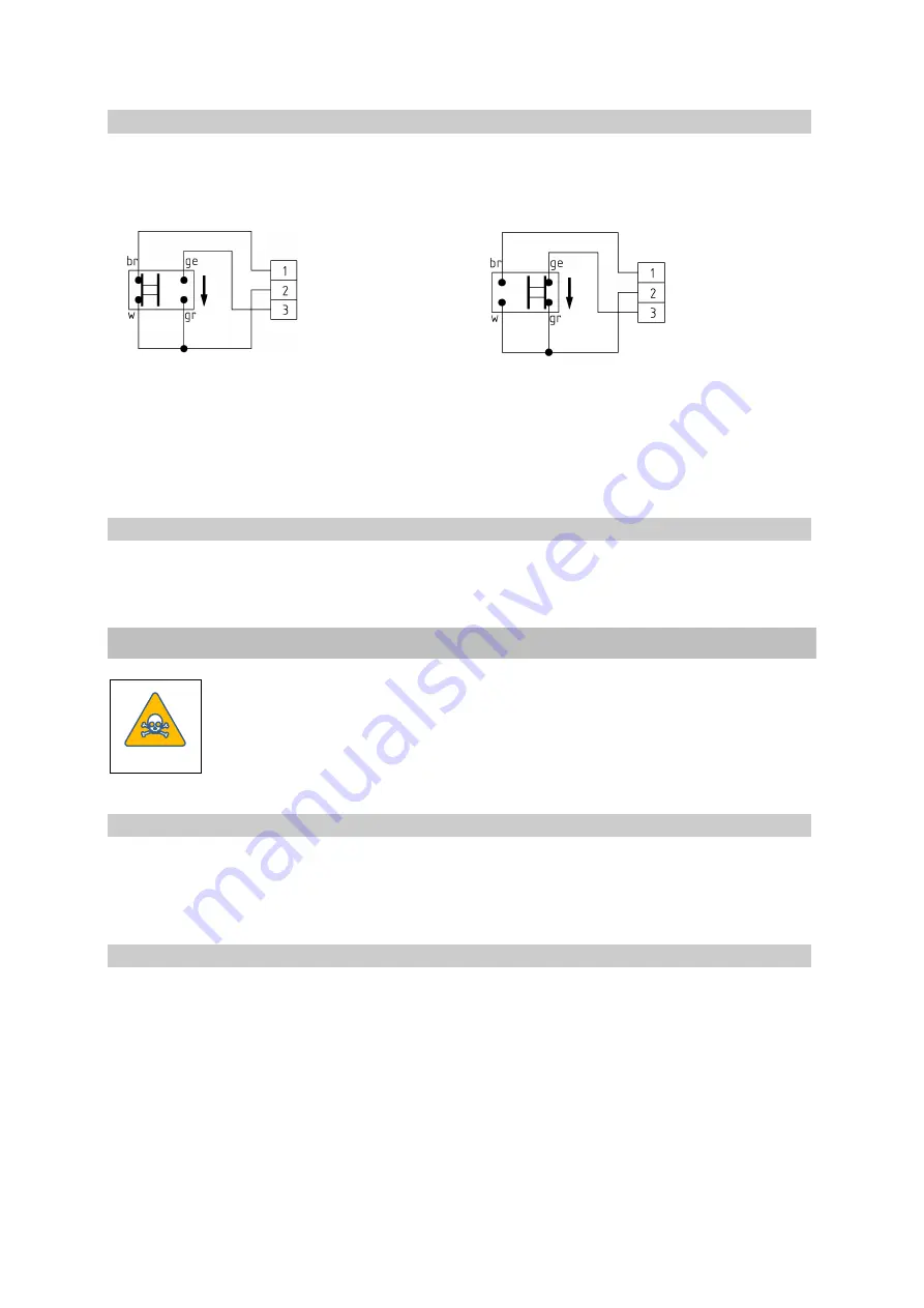
Contact position and wiring diagram:
Float above the switch
Float below the switch
We recommend to use customary RC combinations or a suitable Varistor
(e.g. 0,1 μF/100 Ω) as inductive consumer to extend the contact life of the magnetic switch.
Resistance value (Ω) and power rating (W) depend on customer indications.
We suggest to use silicon cables free of acetic acid for the further connection cable in the
area “connecting housing inside”.
8.2 Primary element
see special data sheet and operating instruction for primary element MRK-
…)
9. Commissioning
Attention danger of life!
Unit may be hot during commissioning and during operation.
Customer can possibly provide safety device.
9.1 Adjustment of indicating flaps
Pass setting magnet (bottom-up) 3 times along the glass plate. The flaps above the zero
mark are white and the flaps below the zero mark are red.
(see figure in chapter 8.4)
9.2 Commissioning of unit together with the boiler
Check specifications of material, pressure and temperature!
•
Close drain valve (A) / plug (6) (see sketch chapter 5).
•
Open shutoff valves W+D.
•
Check position of magnetic switch (2) in operating condition and adjust the height if
necessary
Danger


