background image

1.3  Safety at work 

Before installation or carrying out maintenance work on the device, safe access 
must  be  ensured  and  a  secure  working  area  with  sufficient  lighting  must  be 
defined and marked out.  Always use lifting equipment for heavy loads! 


Before  starting  any  work,  carefully  check  which  liquids  or  gases  are  or  have  been  in  the 
pipeline. (flammable substances, irritating substances, substances hazardous to health) When 
opening or  dismantling the device,  residues of the medium can escape. Subsequent fumes 
are  also  possible  in  unpressurized  and  cold  systems.  Use  designated  PPE  such  as  safety 
goggles and respiratory protection! 

Special attention must be paid to the condition of the environment around the installation or 
maintenance site. Be aware of e.g.: potentially explosive atmospheres, lack of oxygen in tanks 
and pits, dangerous gases/liquids, extreme temperatures, hot surfaces, fire hazard (e.g. during 
welding) and moving machine and system components. Protect yourself from excessive noise 
by taking the required protective measures. 

For  all  maintenance  work  or  new  installations,  on  new  or  existing  boilers  or  vessels,  it  is 
imperative to check that the boiler or vessel has been depressurised and that the pressure has 
been safely reduced to atmospheric pressure. In principle, no system should be regarded as 
unpressurized even if indicated by pressure measuring devices such as pressure gauges or 
sensors.  When releasing  the  pressure, make  sure  that  no  persons  are  in  the  release  area. 
Carefully check whether you and/or other persons in the vicinity need PPE to protect yourself 
from external influences such as high and low temperatures, radiation, noise, danger to eyes, 
loose objects that can fall down or chemicals.  

There is always a risk of injury when handling large and/or heavy equipment. Observe the load 
handling  regulation  as  a  minimum  requirement  for  working  with  loads.  Avoid  handling  the 
device with your own physical force, e.g. by lifting, pulling, carrying, pushing or supporting it, 
especially to prevent back injuries. Use lifting equipment to move heavy and bulky equipment 
in  accordance  with  Article  1,  Section  2  of  the  German  Load  Handling  Regulation 
(LasthandhabV). 

Under normal operating conditions the surface of the device can become very 
hot!  Under  the  maximum  operating  conditions,  the  surface  temperature  can 
exceed 350°C. After shutting off or, if necessary, shutting down the boiler, wait 
until the temperature has normalized to room level. To avoid the risk of burns 
and scalds, always use PPE including safety goggles! 


Danger 


Caution 

hot! 

Summary of Contents for SMLC2

Page 1: ...Edition 12 2020 D 08 B 51037 EN 00 INSTALLATION AND OPERATING INSTRUCTIONS SMLC2 for use with the level probe EL030 or EL19 2 or the multirodprobes EL963 and MS015A B SIL 3 Low water level limiter...

Page 2: ...n of your plants especially in the steam and condensate sector We take care of the modernisation of steam boilers equipped with sophisticated mechanical technology as well as new plants operated with...

Page 3: ...Use in compliance with regulations 9 4 System description 10 4 1 Function 10 4 2 LED Display 11 5 Assembly and Installation 12 5 1 Installation dimensions and descriptions 12 5 2 Installation 13 5 3 E...

Page 4: ...data controller 22 7 2 Device data probe 23 7 3 SIL characteristics 24 7 4 Maximum ratings of potential free contacts 24 7 5 Data plate 24 8 Fault analysis and rectification 25 9 Warranty 25 10 Confo...

Page 5: ...bove tasks IGEMA GmbH accepts no liability for damage to property or personal injury caused by unqualified persons or by failure to observe these installation and operating instructions If no sufficie...

Page 6: ...s The maximum values of the pressure and temperature range of the device must be checked before installation If the maximum allowable operating values of the device are lower than those of the system...

Page 7: ...been depressurised and that the pressure has been safely reduced to atmospheric pressure In principle no system should be regarded as unpressurized even if indicated by pressure measuring devices suc...

Page 8: ...e support e g via a spring suspension device etc This can be attached to the holding strap eyelet on the device When returning goods to IGEMA GmbH the applicable safety and environmental laws accordin...

Page 9: ...fill level the limiter must reliably switch off the boiler s burner control so that no overheating of the boiler can occur and thus injury to people or damage to installations is prevented The prescr...

Page 10: ...the alarm delay time set 4s 8s 12s 16s the output of the safety chain will be switched off safe operation mode and the LED ALARM red remains permanently lit The factory setting for the alarm delay tim...

Page 11: ...perating mode sound operation Flashing green LED 1 Hz low voltage Uv 180V Permanent red LED Level has been below electrode for more than 4 8 12 16 sec Returns to normal operating mode if electrode is...

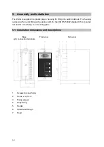
Page 12: ...gned for quick fitting with a spring catch for the DIN EN 50022 standard 35 mm carrier rail and for screw fixing on a mounting plate 5 1 Installation dimensions and descriptions Base Front view Side v...

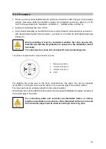
Page 13: ...point 2 in the holder 5 with 4 3 mm drill bit Fit holder 5 on base plate with two M4 screws 5 3 Electrical connection The device terminal strip is live during operation Before working on the device di...

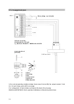
Page 14: ...rinted at the back of the housing EL968 and MS015A B check separate Installation and Operating instructions SMHL2 Safety chain Signalling EL030 oder EL19 2 electrical connection shielded cable 4 x 0 7...

Page 15: ...installation side if necessary The cable must not come into contact with heat conducting parts The probe is equipped with a plug connector 4 pole For aligning the probe plug to the local circumstances...

Page 16: ...both parts by means of the enclosed M4 set screw with AF2 hexagon socket Screwing in the electrode Release screw 1 and pull off electrode plug 2 Clean and check sealing surfaces Insert new sealing rin...

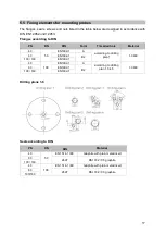
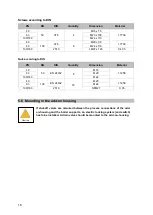
Page 17: ...40 50 EN1092 1 A according to drilling plan 1 1 0460 63 EN1092 1 B2 100 160 EN1092 1 40 100 EN1092 1 A according to drilling plan 1 3 4 5 1 0460 63 EN1092 1 B2 100 160 EN1092 1 Drilling plans 1 6 Seal...

Page 18: ...DIN PN DN DIN Quantity Dimension Material 40 50 EN 24032 8 M16 1 7258 63 M20 100 160 M24 40 100 EN 24032 16 M20 1 7258 63 M24 100 160 2510 NFM27 C 35 5 6 Mounting in the add on housing If shut off val...

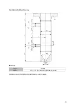
Page 19: ...19 Illustration of add on housing Materials Flange 1 0460 Pipes St35 8 16 Mo 3 according to pressure range Stainless steel and ASME compliant materials upon request...

Page 20: ...60 100 155 160 165 Process connection M1 PN DN DIN DIN sealing form 16 50 100 DIN EN 1092 1 Type 11 Form B1 25 40 63 Form B2 100 160 Process connection M2 PN DN DIN DIN sealing form 16 20 DIN EN 1092...

Page 21: ...rew the probe carefully Remove the electrode extension 9 by unscrewing the grub screw Carefully clamp electrode extension 9 directly at the point to be shortened and shorten it carefully with a suitab...

Page 22: ...w the LEDs see diagram The switch off time can be adjusted as shown in the table DIP switch Switch off time 1 2 on on 4 s off on 8 s on off 12 s off off 16 s 7 Technical data 7 1 Device data controlle...

Page 23: ...bar 20 32 50 80 100 160 250 Max allowable temp TS C 214 239 265 296 312 346 367 Construction dimension Y mm 125 125 Mechanical connection Thread G Power connection Plug connection with screw terminals...

Page 24: ...loads Use contactor Additional fault reporting Switching voltage max 250 V AC max 25 V DC 300 V DC Switching current max 6 A ohmic 6 A 0 1 A Inductive larger loads Use contactor In the case of the pr...

Page 25: ...cable short circuit or cable break check measuring cable Check cap 4 2 too 9 Warranty In addition to the statutory warranty we give a 24 month warranty on our products The prerequisite is proper hand...

Page 26: ...26 10 Conformity declaration...

Page 27: ...27 11 Certificates PED Type Examination...

Page 28: ...28 SIL 3 Zertifizierung...

Page 29: ...r level gauges always yes yes LLW Limiter always yes no LLW Limiter 24h yes no Level control 24h 72h yes yes HHW prevention 24h 72h yes no TDS limitation 72h yes no Direktanzeiger sind Ger te bei dene...

Page 30: ...30...

Page 31: ...31...

Page 32: ...32 Antwerpener Str 1 Fon 49 2501 92424 0 48163 M nster Fax 49 2501 92424 99 Deutschland info igema com www igema com IGEMA GmbH...

Reviews: