background image


REFRIGERATION LTD 


www.igloorefrigeration.com

 | 

Pastry Display Cases


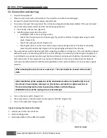
3.3. Connection and start-up 


Unpack the equipment. 


Place the unit on an even and hard base. Then level the unit with the levelling legs. 


Remove the protection foil from display case elements. 


To securely transport the equipment, the unit may be shipped partially disassembled. If the user received 
the unit partially disassembled, perform the following operations: 
1.


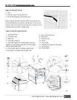
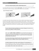
Place hooks in frame rails. (Figure 2) 

2.


Install the glass elements in this order: 

o


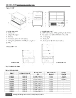
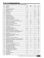
Install glass sides to the rack. (Figure 4/3) 

o


Mount the front glass pane in the pane grip (Figure 4/4) and attach to glass sides using 3-sided 
angle. (Figure 4/6) 

o


Mount the upper glass shelf. (Figure 4/1) 

o


Mount glass shelves on the inner surface and on the rack (Figure 4/12). The shelves should be 
placed on silicone elements (Figure 4/13) to prevent glass elements from moving. 


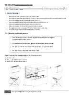
The equipment should be cleaned right after unpacking and before turning it on. The unit should be cleaned 
with warm water not exceeding 40°C with a neutral detergent. For washing and cleaning the equipment, it 
is prohibited to use products containing chlorine and sodium varieties, which destroy the protective layer 
and components of the equipment! Any residue of adhesives or silicone on metal elements should be 
removed only with extraction naphtha (not applicable to items made of plastic). Do not use other organic 
solvents. 

When cleaning the unit, do not use water jet.  The unit should be cleaned with a moist 
cloth. 


After installation of the equipment at the destination location it should be left to rest 
for at least 2 hours before turning it on (for devices with built-in compressor) to set 
the level of refrigerant in order to prevent problems with starting up. 
WARNING: Keep out the cooling circuit from damage! 


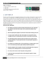
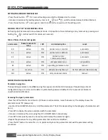
Turn on the main switch. (Figure 5/1) 


The temperature on the thermostat control panel is PRE SET. (Figure 5/3) 


Turn on the light switch. (Figure 5/2) 


Hook on angle 

Figure 2 placing the hooks in the frame 
1 – Vertical post of the internal frame 
2 – Hook mounting holes 
3 – Hook (adjustable to three different angles) 

Summary of Contents for CURP3

Page 1: ...Pastry Display Cases Models CURP series CURLP CURHP CURP Instruction Manual Tel 416 663 3051 Fax 416 663 5793 Toll Free 1 888 408 8819 124 Norfinch Dr Toronto ON M3N 1X1 REFRIGERATION LTD ...

Page 2: ...on 9 5 MAINTENANCE 12 5 1 Cleaning and maintenance 12 6 SERVICE 14 6 1 Faults identification and repair 14 6 2 Service 15 List of Figures Figure 1 CURP 4 Figure 2 placing the hooks in the frame 6 Figure 3 Hook height control 7 Figure 4 Assemble of glass elements 7 Figure 5 Control panel 8 Figure 6 Carel thermostat control panel 9 Figure 7 Manner of assembling pulling out the blow in and suction 12...

Page 3: ...iption of the unit CURP series display cases have a dynamic cooling system All units are equipped with automatic condensate evaporation and automatic defrosting The electronic thermostat cooperates module to monitor and send signals when the temperature inside the equipment gets too low or too high They can be supplied with self contained or remote compressors Glass shelves fixed on the frame make...

Page 4: ...legs 11 Serial plate 12 Control panel thermostat switches 2 3 Technical data Table 1 Technical data Model Voltage V Hz Ph Rated Current A Max shelf load lbs kg Weight lbs kg CURP2 115 60 1 8 max fuse 15 22 10 198 90 CURP3 115 60 1 8 max fuse 15 22 10 308 140 CURP4 115 60 1 12 max fuse 15 22 10 397 180 CURLP2 115 60 1 8 max fuse 15 22 10 CURLP3 115 60 1 8 max fuse 15 22 10 CURLP4 115 60 1 12 max fu...

Page 5: ...re protection efficiency with results of measures performed according to binding regulations 3 2 Unit Location Remove cardboard angles and protective foil Install the unit on a strong and leveled surface To ensure proper operation of the unit it must be leveled from front to back and left to right Unit may malfunction if improperly leveled Be sure there is sufficient ventilation around the entire ...

Page 6: ... turning it on The unit should be cleaned with warm water not exceeding 40 C with a neutral detergent For washing and cleaning the equipment it is prohibited to use products containing chlorine and sodium varieties which destroy the protective layer and components of the equipment Any residue of adhesives or silicone on metal elements should be removed only with extraction naphtha not applicable t...

Page 7: ...ack and place it in the suitable position and at the suitable angle 7 Acorn nut of the screw 8 Silicon pad 9 Plasticizer pad 10 Screw 11 Inner frame 12 Display glass shelves of the frame 13 Bumper pads 14 Inner surface Figure 4 Assemble of glass elements 1 Upper glass shelf 2 Front glass pane 3 Glass side 4 Front glass pane grip 5 Two sided angle for mounting of glass panes to CURP4 connecting the...

Page 8: ...equipment and shall ensure proper water condensate outflow during defrosting After transporting the equipment wait about 2 hours before starting up the unit To ensure proper conditions for the stored products do not load the shelves completely Ensure even load of shelves and not to exceed the maximum load The first filling of shelves should be performed after the unit reached desired cooling tempe...

Page 9: ...s when the actuation of the ventilators is delayed by external disengagement or when another procedure is in progress Diode 3 Defrosting This symbol is visible when the defrosting function is activated It blinks when the actuation is delayed by external disengagement or when another procedure is in progress Diode 4 Alarm This symbol is visible when the alarm is activated Diode 5 Current temperatur...

Page 10: ...eter error manual Ed not active ON defrost ended by timeout On first defrost ended correctly CHt active ON dirty condenser alarm manual MODIFYING THE PARAMETERS Parameter navigation The operating parameters modifiable using the keypad are divided into two types frequent type F and configuration type C Access to the latter is protected by password default 22 to prevent accidental or unauthorized mo...

Page 11: ...ost temperature set point 12 0 C 50 130 dP maximum defrost duration 30 min 1 199 d4 defrost when switching the instrument on 0 0 1 d5 defrost delay on power up or when enabled by digital input 0 min 0 199 d6 freeze control temperature display during defrost 1 0 1 dd dripping time 2 min 0 15 d8 alarm bypass time after defrost 2 h 0 15 d9 defrost priority over compressor protectors 0 0 1 d defrost p...

Page 12: ... with warm water and mild soap Make sure to cover the fan motor to prevent moisture damage Dore gaskets shelves and supports should be cleaned on a regular basis Fan blades and guards should be cleaned with a soft cloth 5 1 Cleaning and maintenance All maintenance services need to be performed after disconnecting the equipment from power supply Protect electrical components against any damage or w...

Page 13: ...ed to use vacuum cleaner or compressed nitrogen to suck blow the dirt from between lamellas The seller shall not be held responsible for any condenser damages in the case of non observance of condenser cleaning instructions This concerns CURP2 CURLP2 and CURHP2 Door seal should be cleaned solely with clean water without any cleansing agents and it should be thoroughly dried The seal cannot get int...

Page 14: ...pty the condensate container The equipment does not reach the proper temperature the light is on Make sure that The main switch is on Temperature setting on the thermostat is properly set Thermostat works properly The condenser is clean if necessary clean the condenser Ambient temperature does not exceed 25ºC Enough time has passed for products to be cooled Ventilation holes are not blocked Relati...

Page 15: ...rcuit This phenomenon constitutes a technical feature of cooling devices and does not signify equipment failure Steam precipitation on glasses is normal in the event of high relative air humidity exceeding 55 and does not require calling for service 6 2 Service IGLOO Refrigeration service Telephone number 416 663 3051 or toll free 1 888 408 8819 E mail service igloo400 com If after checking points...

Reviews: