Chapter 2 Hardware
Power Supply Removal
Always observe proper ESD precautions and use an ESD wrist strap when working on
components inside the terminal.
To remove the power supply:
1. Open the main door and power off the cabinet.
2. Open the lower door.
3. Remove the connection on the power supply from the AC Box.
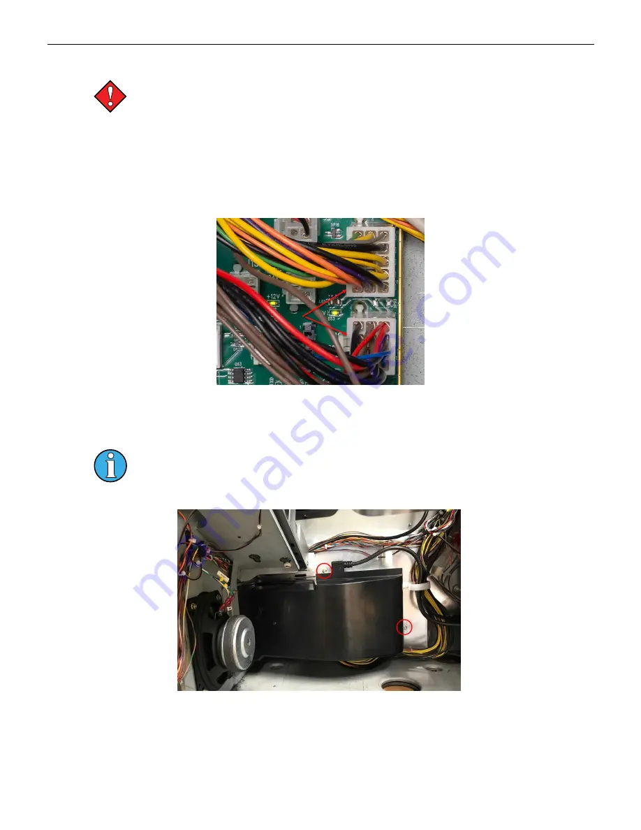
4. Disconnect J1 & J2 at the cabinet controller board.
Figure 2-9 Power Supply Connections to Cabinet Controller Board
5. Remove the wiring from the harness guides and remove zip ties, if any.
6. Disconnect the power connection going to the Brain Box.
The shroud and power supply are removed as a single unit. Once removed from the
cabinet, the shroud can be detached from the power supply.
7. Remove the two M4 nuts and remove the power supply and shroud from the cabinet.
Figure 2-10 Power Supply Removal
34
Cobalt™ 27
Summary of Contents for Cobalt 27
Page 5: ...CFInit 85 Appendix A Stand Mounting 87 Cobalt 27 5...
Page 6: ...6 Cobalt 27...
Page 12: ...Chapter 1 Cobalt Overview Dimensions Figure 1 2 Dimensions 12 Cobalt 27...
Page 26: ...26 Cobalt 27 Chapter 1 Cobalt Overview...
Page 40: ...Chapter 2 Hardware Figure 2 16 Cabinet Controller Board Connectors 40 Cobalt 27...
Page 76: ...76 Cobalt 27 Chapter 2 Hardware...
Page 88: ...Appendix A Stand Mounting Figure A 2 Stand Drill Pattern 88 Cobalt 27...


