Chapter 2 Hardware
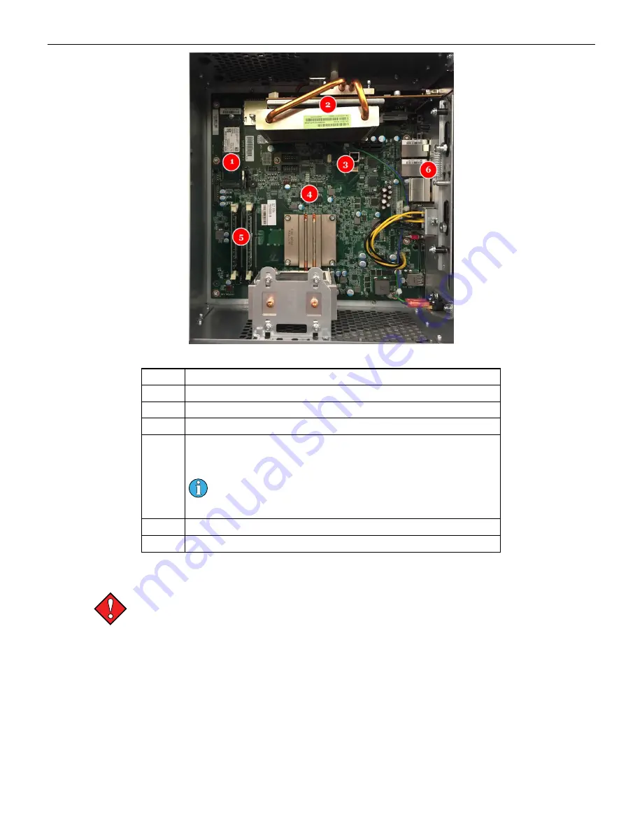
Figure 2-14 AVP 4.0+ Brain Box Components
Number
Description
1
Solid State Drive in M.2 format
2
AMD E9260 GPU (video card)
3
USB-B Port
4
AP PROM
This chip contains a read only AP_Image directory which
authenticates the boot image in the root directory.
APR00004 or later must be used and must be compatible with
the boot release version. Refer to the theme overview for more
information.
5
Memory Slots
6
On-board Audio
Brain Box Removal
Always observe proper ESD precautions and use an ESD wrist strap when working on
components inside the terminal.
To remove the BrainBox from the terminal:
1. Open the main door and power off the cabinet.
2. Disconnect the Power In connection.
3. Disconnect the PCI-E Connection, USB connection(s), Audio connection, and the 4 mini
display port connections.
4. Turn the key to unlock the brainbox, and slide that latch to the unlock the brainbox.
5. Slide the brainbox forward and remove it from the cabinet.
To open the lid on the brainbox, unlock the lid and slide the latch to open.
38
Cobalt™ 27
Summary of Contents for Cobalt 27
Page 5: ...CFInit 85 Appendix A Stand Mounting 87 Cobalt 27 5...
Page 6: ...6 Cobalt 27...
Page 12: ...Chapter 1 Cobalt Overview Dimensions Figure 1 2 Dimensions 12 Cobalt 27...
Page 26: ...26 Cobalt 27 Chapter 1 Cobalt Overview...
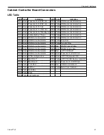
Page 40: ...Chapter 2 Hardware Figure 2 16 Cabinet Controller Board Connectors 40 Cobalt 27...
Page 76: ...76 Cobalt 27 Chapter 2 Hardware...
Page 88: ...Appendix A Stand Mounting Figure A 2 Stand Drill Pattern 88 Cobalt 27...


