Chapter 2 Hardware
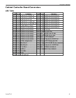
Connector Table
Connector
Description
Connector
Description
J1
3.3VDC, 5V_STBY, 12VDC Input J25
Tell Tale Battery
J2
-12 VDC, 5VDC, 24VDC Input
J26
Tell Tale Diagnostic
J3
24VDC Output
J27
Main 1, Front, Bill, Drop Door
JPR & W2G Key Switches
Cabinet Power Switch
Bass Speaker Out
J5
12VDC, 24VDC Output
J28
Main Door 2 (optic receiver)
J6
Topper Media Controller 12VDC
(pre-wired)
J29
Coin Acceptor (if present)
J7
12VDC, 24VDC Output
J30
USB upstream from Brain Box
J8
5VDC standby
J31
USB dual downstream
J9
5VDC standby
J32
USB dual downstream
J10
Bill Validator Bezel 24VDC
Printer Bezel 24VDC
USB Charger 12VDC
Audio AMP 24VDC
Bass Speaker In
Main LCD 24VDC
Top LCD 24VDC
DPP 12VDC
J33
USB dual downstream
J11
Belly Door Logo Light 24VDC
Bill Validator 12VDC
Printer 24VDC
J34
COMM 1
J12
-12VDC Output
J35
COMM 2
J13
12VDC, 24VDC Output
J36
Unused
J16
PCIe to Brain Box
J37
COMM 4
J18
Hard Meters
J38
SWD Port
J19
FPGA Program
J40
Button Deck
J20
FPGA JTAG
J41
Main & Top LCD Trim Lighting
J21
Candle 12VDC
Video Topper 24VDC
J43
Belly Light (unused)
J22
Security Door
Cashbox Present Door
Internal Key
Main Door 2 (optic emitter)
J45
COMM 3
J23
Loss Limit
J48
Unused
J24
Bell 24VDC (if present)
U12 & U13 EEPROM (Cabinet Memory)
42
Cobalt™ 27
Summary of Contents for Cobalt 27
Page 5: ...CFInit 85 Appendix A Stand Mounting 87 Cobalt 27 5...
Page 6: ...6 Cobalt 27...
Page 12: ...Chapter 1 Cobalt Overview Dimensions Figure 1 2 Dimensions 12 Cobalt 27...
Page 26: ...26 Cobalt 27 Chapter 1 Cobalt Overview...
Page 40: ...Chapter 2 Hardware Figure 2 16 Cabinet Controller Board Connectors 40 Cobalt 27...
Page 76: ...76 Cobalt 27 Chapter 2 Hardware...
Page 88: ...Appendix A Stand Mounting Figure A 2 Stand Drill Pattern 88 Cobalt 27...


