Initial Operation
D8-3_EN
– V1.0
10/14
4
Initial Operation
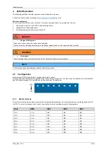
The following describes the initial operation, which makes the start easy.
Connect the whole system according to
Minimum equipment
To control a motor with the motor controller, a minimum equipment has to be provided by the user:
1.
Power supply with 24 V up to 48 V and connecting cables
2.
Stepper motor with suitable cable
3.
Switches/signa generator/microcontroller/PLC
WARNING!
•
Fire hazard
Faulty settings of the motor controller can lead to extremely high motor temperatures.
NOTE
A faulty connection can damage or destroy the motor controller
4.1
Configuration
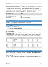
8 dip switches (SW) are available for configuring the motor control.
These can be used to preselect the emitted motor current during a movement, the step mode, the emitted current at standstill
and the fixed motor speed in Loop Mode as well as executing the autotuning.
4.1.1
Motor Current
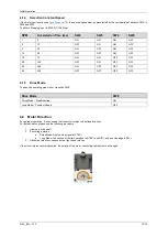
The motor current output during a movement can be adjusted depending on the connected motor by combining switches SW1
to SW3. To output the desired motor current, the switches must be combined using the following table.
Peak
RMS
SW1
SW2
SW3
1,5 A
1,1 A
ON
ON
ON
1,8 A
1,3 A
OFF
ON
ON
2,2 A
1,6 A
ON
OFF
ON
2,8 A
2,0 A
OFF
OFF
ON
3,5 A
2,5 A
ON
ON
OFF
4,0 A
2,9 A
OFF
ON
OFF
4,8 A
3,4 A
ON
OFF
OFF
5,5 A
4,0 A
OFF
OFF
OFF
DANGER!
•
Danger of falling load
Never work under unsecured vertical axes and loads.
Secure the axis or load against falling by a mechanical safety device or other approved safety method.

