


Initial Operation
D9_EN
– V1.2
11/15
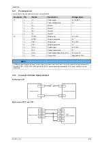
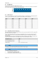
4.1
Configuration
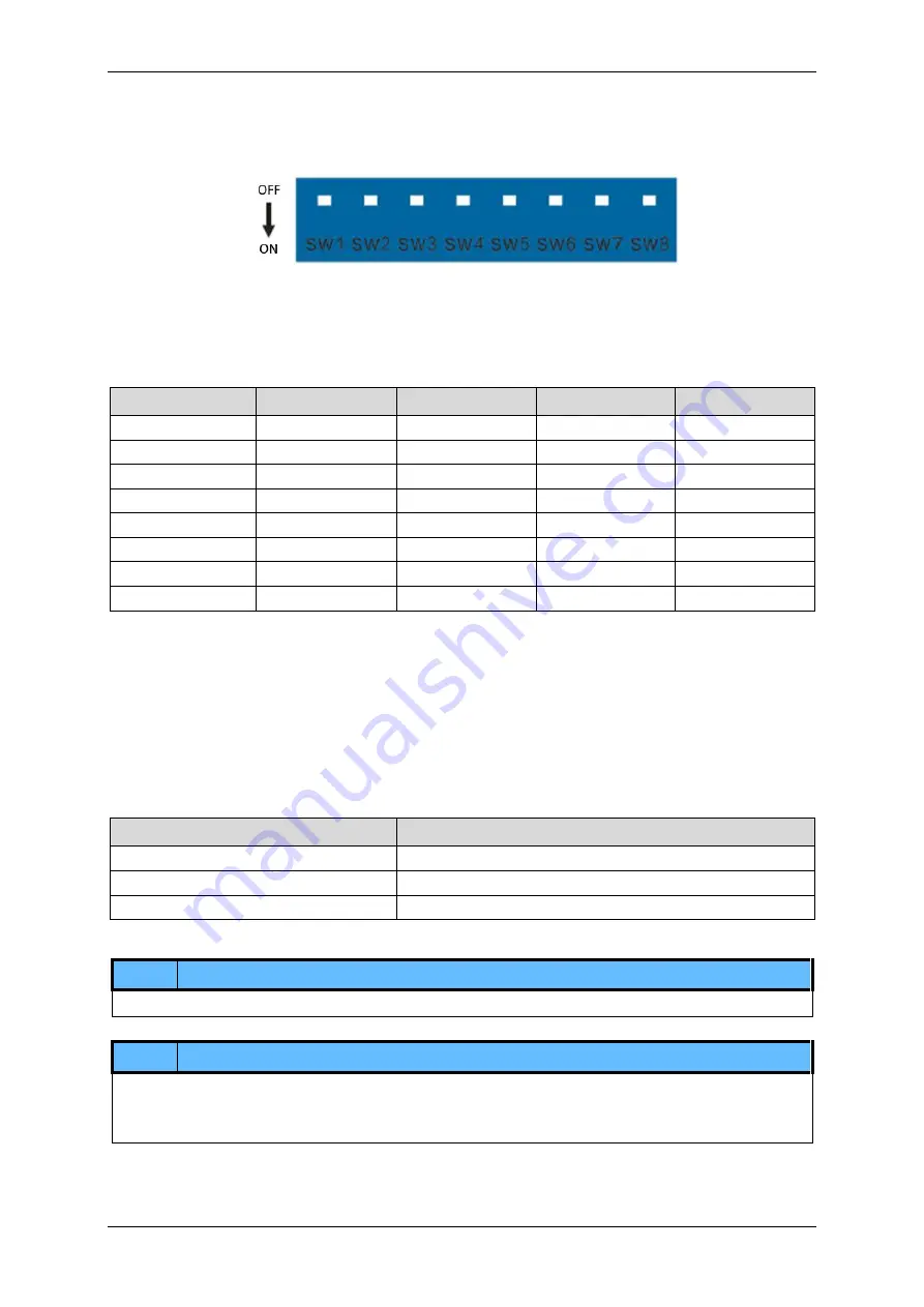
8 dip switches (SW) are available for configuring the motor control.
These can be used to preselect the emitted motor current during a movement, the step mode, the emitted current at standstill
and the fixed motor speed in jog mode as well as executing the autotuning.
4.1.1
Motor Current
The motor current output during a movement can be adjusted depending on the connected motor by combining switches SW1
to SW3. To output the desired motor current, the switches must be combined using the following table.
Peak
RMS
SW1
SW2
SW3
3,0 A
2,2 A
ON
ON
ON
4,2 A
3,0 A
OFF
ON
ON
4,8 A
3,4 A
ON
OFF
ON
5,6 A
4,0 A
OFF
OFF
ON
6,5 A
4,6 A
ON
ON
OFF
7,2 A
5,1 A
OFF
ON
OFF
8,4 A
6,0 A
ON
OFF
OFF
9,8 A
7,0 A
OFF
OFF
OFF
4.1.2
Standstill Current and Autotuning
If the enable signal is set but no motion command is present, the motor current set via switches SW1 to SW3 is reduced to 50%
(SW7 ON) or 90% (SW7 OFF) at standstill.
The auto-tuning function allows the motor controller to be optimally adapted to the connected motor. If this is performed, the
internal control parameters are tuned to ensure a high torque output even at high rpm, as well as generally quiet and low-
vibration operation.
If autotuning is started, the green status LED switches off for the duration of the parameter determination. Autotuning has been
successfully performed when the green status LED lights up again. This process takes approx. 3 seconds.
Standstill Current
SW7
50 % of preselected Motor Current-
ON
90 % of preselected Motor Current-
OFF
Start Autotuning
OFF
– ON – OFF within 1 second
NOTE
Autotuning can only be started if switch SW7 has been set to OFF for at least 1 second.
NOTE
Autotuning should always be performed when:
-
The motor control unit is used for the first time.
-
The motor controller's supply voltage changes
-
A different motor is connected to the motor controller


