


Execution of Movements
D9_EN
– V1.2
13/15
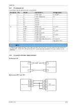
4.2
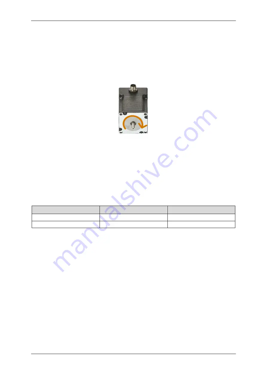
Motor Direction
For a proper operation, it is necessary that the motor rotates in a defined direction.
For determination, please use the following procedure:
1.
View onto drive shaft
2.
Executing a motion
a.
Pulse Mode: Apply a step signal at STEP+
b.
Jog Mode: Apply a constant signal at STEP+
3.
Clockwise rotation corresponds to a right-hand rotation
If the motor rotates counter-clockwise, the polarity of the motor connecting cables must be changed.
5
Execution of Movements
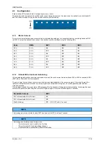
5.1
Pulse Mode
– Step/Direction
To execute a movement in pulse mode, a 5 V to 24 V signal must be permanently applied to the EN+ input.
If a square wave signal is applied to the STEP+ input, a clockwise motor step is executed with each negative signal edge. To
execute a counter-clockwise movement, a 5 V to 24 V signal must be applied to DIR+.
A 5 ms delay must be implemented between setting the EN+ input high and emitting a signal to the STEP+ input.
To be able to change the rotation direction, the frequency signal at STEP+ must be dropped to a zero signal (0 V, 0 frequency)
and a 5 V to 24 V signal must be applied to DIR+ at least 5 µs before a frequency signal is output to STEP+ again.
Rotation direction
Signal at STEP+
Signal at DIR+
Clockwise
Frequency signal, 5 V up to 24 V
0 V
Counter-Clockwise
Frequency signal, 5 V up to 24 V
5 V up to 24 V


