


Execution of Movements
D9_EN
– V1.2
14/15
5.2
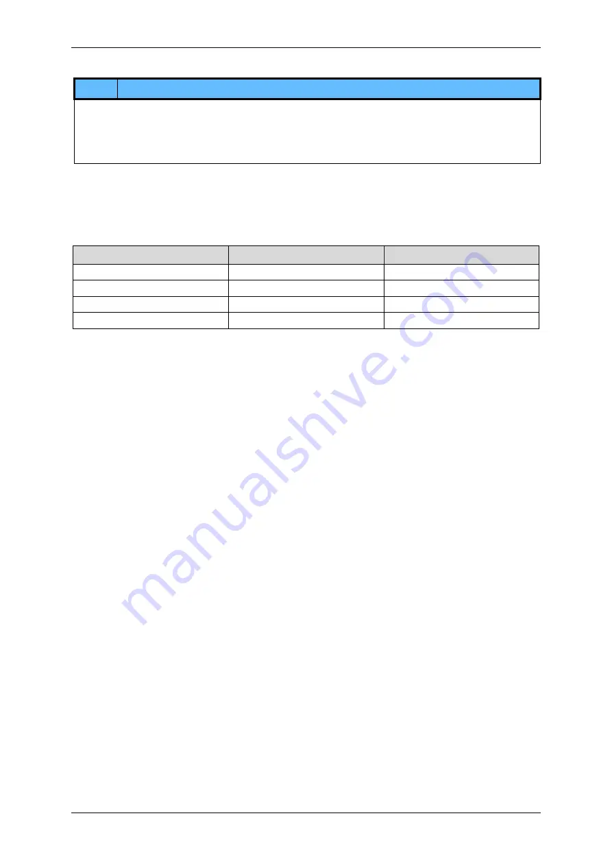
Jog Mode
– Constant Rotation Speed
Note
It is recommended to use this mode only for pitches/feed rates ≤ 60 mm per drive shaft revolution.
For higher pitches/feed rates, acceleration values of > 2000 mm/s² can be achieved due to the fixed acceleration and
deceleration time.
Applications that are to be operated in this mode must be approved by the customer.
To execute a movement in jog mode, a 5 V to 24 V signal must be permanently applied to the EN+ input.
If a 5 V to 24 V signal is applied to the STEP+ input, a clockwise rotation is executed at the pre-set speed. To execute a
counter-clockwise movement, a 5 V to 24 V signal must be applied to DIR+.
A 5 ms delay must be implemented between setting the EN+ input high and emitting a signal to the STEP+ or DIR+ input.
Acceleration like deceleration is set to a fixed time value of 250 ms.
Rotation direction
Signal at STEP+
Signal at DIR+
Clockwise
5 V up to 24 V
0 V
Counter-Clockwise
0 V
5 V up to 24 V
No Movement/Stop
0 V
0 V
No Movement/Stop
5 V up to 24 V
5 V up to 24 V


