background image

Table of contents 

D9_EN 

– V1.2 

2/15 

Table of Contents 

1


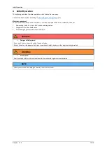
Safety Instructions, Protective Measures and Guidelines............................ 3


1.1


Important Instructions ........................................................................ 3


1.2


Qualified Personnel ........................................................................... 3


1.3


Maintenance ...................................................................................... 3


1.4


Safety Instructions ............................................................................. 4


1.4.1


Classification of Information .............................................................. 4


1.5


Electromagnetic Compatibility ........................................................... 4


2


Product Overview ............................................................................................. 5


2.1


Technical Data .................................................................................. 5


2.1.1


Dimensions ....................................................................................... 5


2.1.2


Mechanical Data ............................................................................... 5


2.1.3


Electrical Data ................................................................................... 6


2.1.4


Environmental conditions .................................................................. 6


3


Installation ........................................................................................................ 7


3.1


Mechanical Installation ...................................................................... 7


3.2


Electrical Installation.......................................................................... 7


3.2.1


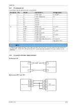
Pin Assignment ................................................................................. 8


3.2.2


Connection Scheme Signal In/Output ............................................... 8


3.3


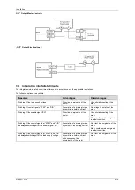
Integration into Safety Circuits .......................................................... 9


4


Initial Operation ...............................................................................................10


4.1


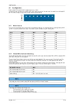
Configuration ....................................................................................11


4.1.1


Motor Current ...................................................................................11


4.1.2


Standstill Current and Autotuning .....................................................11


4.1.3


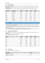
Micro-Stepping .................................................................................12


4.1.4


Selection Constant Speed ................................................................12


4.1.5


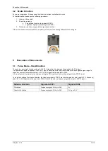
Drive Mode .......................................................................................12


4.2


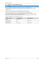
Motor Direction .................................................................................13


5


Execution of Movements ................................................................................13


5.1


Pulse Mode 

– Step/Direction ............................................................13


5.2


Jog Mode 

– Constant Rotation Speed ..............................................14


6


Status and Error Messages ............................................................................15


7


Accessories .....................................................................................................15


8


Service .............................................................................................................15


Summary of Contents for motion Plastics dryve D9

Page 1: ...D9_EN V1 2 1 15 igus motion Plastics dryve D9 Step Direction Stepper Motor Control System Manual V 1 2 Website Motor Shop http www igus eu motorshop Videos Tutorials www igus eu dryve tutorial...

Page 2: ...6 2 1 4 Environmental conditions 6 3 Installation 7 3 1 Mechanical Installation 7 3 2 Electrical Installation 7 3 2 1 Pin Assignment 8 3 2 2 Connection Scheme Signal In Output 8 3 3 Integration into...

Page 3: ...onal injury or damage to property resulting from misuse or unauthorised technical modification of the motor controller igus reserves the right to make changes and improvements to the product or the te...

Page 4: ...t or property damage NOTE Safety instructions marked with NOTE indicate a potential hazardous situation Disregard of the notice may possibly result in property damage 1 5 Electromagnetic Compatibility...

Page 5: ...various additional switches and sensors Simple control With the JOG mode a pre selected speed can be started by simply applying a signal The rotational direction can be changed by connecting a second...

Page 6: ...input signal width Min 50 s Dissipation Loss Max 470 W Digital Inputs Outputs Galvanically Separated by Optocoupler Voltage supply output Out Max 30 V Current output Out Max 100 mA Boot up time 2 s Ca...

Page 7: ...tallation The motor controller is constructed for use with direct currents Every voltage mentioned in this manual can be regarded as direct current WARNING Risk of injury Make sure that an emergency s...

Page 8: ...IR Motion input 5 V to 24 V 4 DIR Motion input ground 0 V 5 EN Enable signal 5 V to 24 V 6 EN Enable signal ground 0 V 7 Out Power supply status output Error 5 V up to 24 V 8 Out Output Error Depended...

Page 9: ...rrent No voltage free status of the motor Switching off the enable signal EN Direct de energisation of the motor Uncontrolled coasting of the motor Motor could remain energised in a fault condition Sw...

Page 10: ...he user 1 Power supply with 24 V up to 48 V and connecting cables 2 Stepper motor with suitable cable 3 Switches signa generator microcontroller PLC WARNING Fire hazard Faulty settings of the motor co...

Page 11: ...mmand is present the motor current set via switches SW1 to SW3 is reduced to 50 SW7 ON or 90 SW7 OFF at standstill The auto tuning function allows the motor controller to be optimally adapted to the c...

Page 12: ...be the identical If for example 200 micro steps per motor revolution are set in the motor controller but 400 micro steps per motor revolution are set in the master controller and the master controller...

Page 13: ...ode a 5 V to 24 V signal must be permanently applied to the EN input If a square wave signal is applied to the STEP input a clockwise motor step is executed with each negative signal edge To execute a...

Page 14: ...a 5 V to 24 V signal must be permanently applied to the EN input If a 5 V to 24 V signal is applied to the STEP input a clockwise rotation is executed at the pre set speed To execute a counter clockwi...

Page 15: ...SET 1 Top Hat rail mounting clip with matching screw Connectors D9 CONNECTOR SET Complete set off all dryve D9 connector plugs 8 Service Customer service de dryve igus net 49 0 2203 9649 845 Technical...

Reviews: