


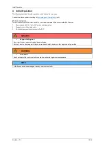

Initial Operation
D9_EN
– V1.2
12/15
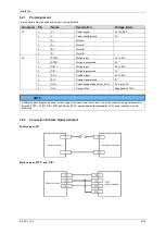
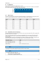
4.1.3
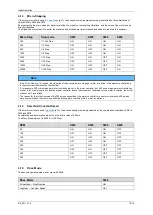
Micro-Stepping
If the motor controller is used in
(p.13), the desired micro step mode must be preselected by the combination of
switch SW4 to SW6 and SW 8.
By preselecting the micro steps per motor revolution, the precision, the resulting vibrations, and the noise of the motor can be
directly influenced.
The higher the micro steps, the better the precision and at the same time vibrations and noise are reduced to a minimum.
Micro Step
Step mode
SW4
SW5
SW6
SW8
200
1/1 Full Step
ON
ON
ON
ON
400
1/2 Step
OFF
ON
ON
ON
800
1/4 Step
ON
OFF
ON
ON
1600
1/8 Step
OFF
OFF
ON
ON
3200
1/16 Step
ON
ON
OFF
ON
6400
1/32 Step
OFF
ON
OFF
ON
12800
1/64 Step
ON
OFF
OFF
ON
25600
1/128 Step
OFF
OFF
OFF
ON
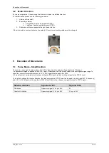
Note
(p.13) is used, the selection of the executed micro steps per motor revolution in the master controller and
in the motor controller must be the identical.
If, for example, 200 micro steps per motor revolution are set in the motor controller, but 400 micro steps per motor revolution
are set in the master controller, and the master controller issues the movement command for one motor revolution, the motor
will execute 2 revolutions.
The reason for this is that instead of the 200 pulses expected by the motor controller for one motor revolution, 400 pulses
were now emitted by the master controller and these were converted into 2 motor revolutions.
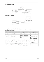
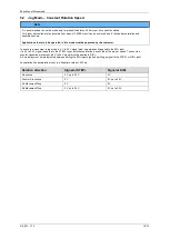
4.1.4
Selection Constant Speed
If the motor controller is used
(p.14), the desired speed must be preselected by the combination of switches SW4 to
SW6 and SW8.
Acceleration and deceleration are set to a fixed time value of 250 ms.
The Micro Stepping is set to 25600 (1/128 Step).
RPM
SW4
SW5
SW6
SW8
50
ON
ON
ON
OFF
100
OFF
ON
ON
OFF
150
ON
OFF
ON
OFF
200
OFF
OFF
ON
OFF
250
ON
ON
OFF
OFF
300
OFF
ON
OFF
OFF
400
ON
OFF
OFF
OFF
500
OFF
OFF
OFF
OFF
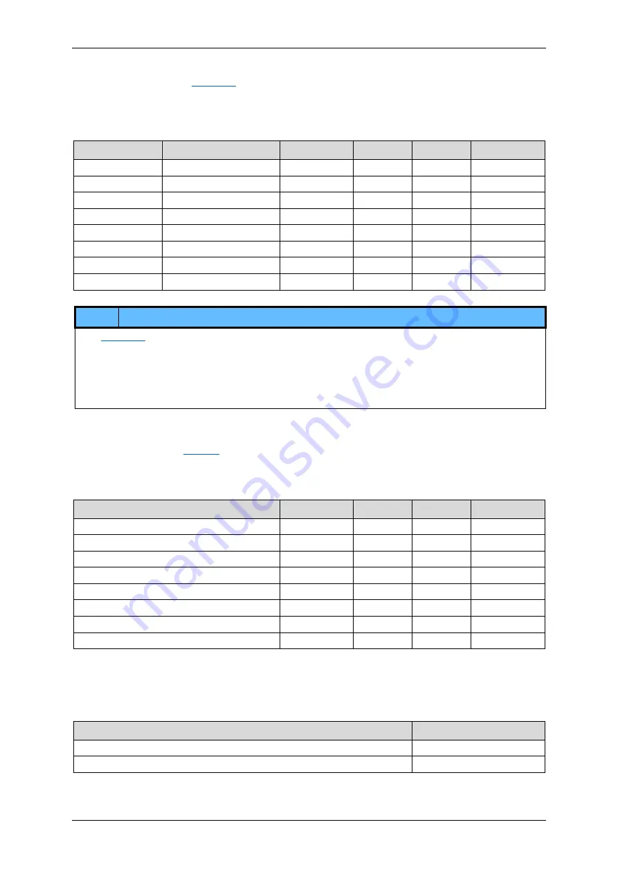
4.1.5
Drive Mode
The desired operating mode is set via switch SW8.
Drive Mode
SW8
Pulse Mode
– Step/Direction
ON
Jog Mode
– Constant Speed
OFF


