Installation
D9_EN
– V1.2
8/15
3.2.1
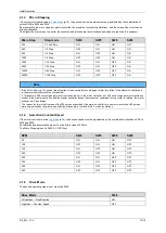
Pin Assignment
The connectors must be wired according to your application.
Connector Pin
Name
Description
Voltage limits
X1
1
V +
Power supply
24 V to 48 V
2
V -
Power supply ground
0 V
3
A +
Motor A
-
4
A -
Motor A/
-
5
B +
Motor B
-
6
B -
Motor B/
-
X2
1
STEP +
Motion input
5 V to 24 V
2
STEP -
Motion input ground
0 V
3
DIR +
Motion input
5 V to 24 V
4
DIR -
Motion input ground
0 V
5
EN +
Enable signal
5 V to 24 V
6
EN -
Enable signal ground
0 V
7
Out+
Power supply status output „Error“
5 V up to 24 V
8
Out-
Output „Error“
Depended on OUT+
NOTE
If different power supplies are used for the supply of the motor (terminal V+ and V-) and the supply of the signal transmitter
(terminal STEP+, STEP-, DIR+, DIR- and EN+ and EN-), a ground potential equalisation of the power supplies must be
performed
3.2.2
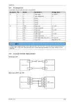
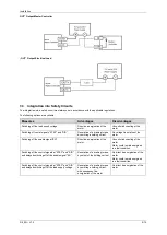
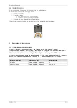
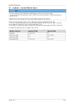
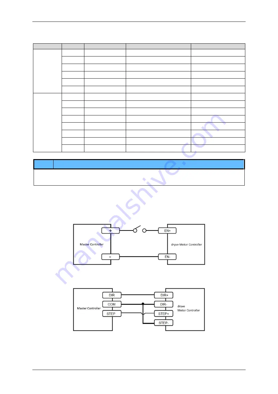
Connection Scheme Signal In/Output
Enable signal „EN“
Motion signal „STEP“ and „DIR“

