3.
Dimensions
3.1
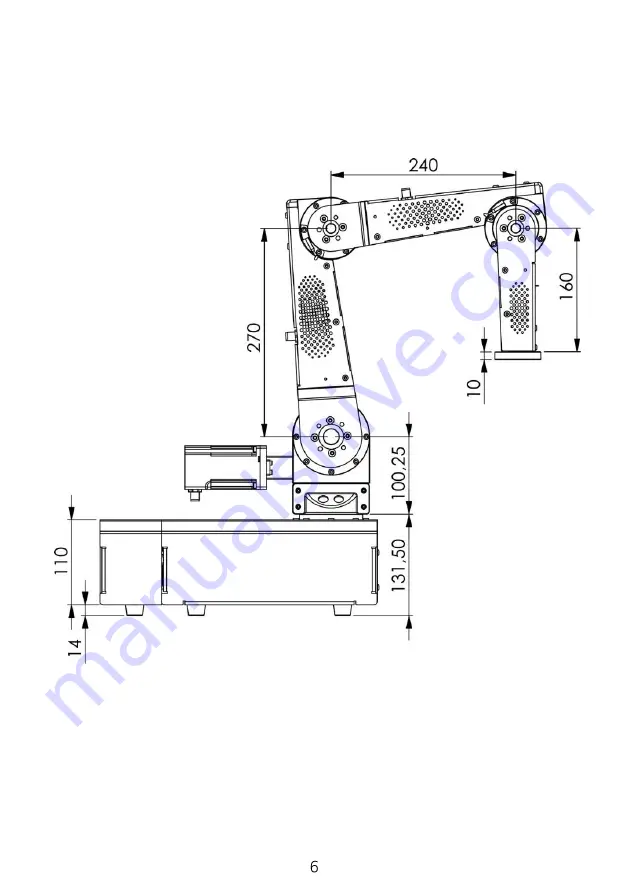
Lateral view
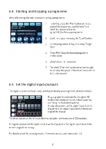
Diagram 1: Side view of the DCi robot. The robot axes (motors) are basically counted from the
robot base. So axis 1 is the vertical axis in the robot base. An effector (e.g., gripper) can be
attached to axis 4/5 (4 or 5-axis version).
A 4-axis robot has a mounting plate instead of the last axis.
Summary of Contents for robolink DCi
Page 1: ......
Page 2: ......
Page 3: ......
Page 4: ...1 Safety instructions ...
Page 5: ...2 Introduction 2 1 Robot components ...
Page 6: ...2 2 Specification ...
Page 10: ...4 2 Digital Inputs Outputs ...
Page 11: ...Diagram 4 Additional internal digital I Os ...
Page 14: ...5 Commissioning ...
Page 15: ...6 Operation 6 1 Reset errors Enable robot ...
Page 16: ...6 2 Manual method of the robot ...
Page 17: ...6 3 Referencing the robot ...
Page 18: ...6 4 Starting and stopping a programme 6 5 Set the digital inputs outputs ...
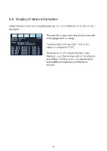
Page 19: ...6 6 Display of status information ...
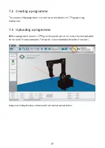
Page 20: ...7 Programming 7 1 Establish connection ...
Page 22: ...8 Integration in safety circuit ...
Page 23: ...9 Interfaces 9 1 Digital inputs and outputs 9 2 PLC interface 9 3 Plug in interface ...
Page 24: ...9 4 CRI interface ...
Page 26: ...11 Troubleshooting and support 11 1 Error codes ...
Page 27: ...11 2 CAN Bus and CPRog status information ...
Page 28: ...11 3 Hardware o o o o o ...
Page 29: ...11 4 Software o ...
Page 30: ...11 5 Support contact ...
Page 31: ......
Page 32: ......


