background image

Summary of Contents for 9NX

Page 1: ...Service Guide for SERIAL NUMBERS BB000011 and up IHI IHIConstruction Machinery Limited PUB No 1 0404...

Page 2: ...HYDRAULIC MINI EXCAVATOR TABLE OF CONTENTS SECTION 1 SPECIFICATIONS SECTION 2 STRUCTURE AND FUNCTION SECTION 3 OPERATION SECTION 4 MAINTENANCE SECTION 6 PERFORMANCE STANDARDS...

Page 3: ...OF CONTENTS Subject Page General specifications 1 1 1 Overall dimensions and working ranges 1 2 1 Rated object handling capacitiestable 1 3 1 Weight breakdown 1 4 1 Engine main date and specifications...

Page 4: ...2 6 8 2400 9 3 2400 DIN6271 6 7 124001 31 9 1800 3 25 1800 Engine model Engine type No of cyl bore x stroke Total piston displacement Rated output Max torque mm L kW min ps rpm N m min kgfomI rpm Mach...

Page 5: ...icable Bucket capacity ISO m3 Side width mm 370 320 220 Weight kg 17 6 16 0 13 0 Heaped 0 022 0 017 0 011 Remarks Standard OPT OPT Number of teeth 4 3 2 Struck 0 015 0 013 0 008 1 Remarks General digg...

Page 6: ...us atrightboomswing Description Crawler shoe width Overall length of crawler Overallwidth of crawler Width Height Rear end swing radius Rear end ground clearance Mini ground clearance 720 1405 485 405...

Page 7: ...aped Long arm 0 017 D E F G H I J K L M N Radius of max digging depth Max digging height Radius of max digging height Max dumping height Radius of max digging height Min dumping height Radius of min d...

Page 8: ...Spec I Weight kg 785 Weight kg 890 This weight is not the mass of the machine body It includes the weight of water fuel blade and others 3 Upper structure I Specification 1 Weight kg 4 Under carriage...

Page 9: ...al 2 cylinder type 2 68 x 72 0 522 23 0 effective 21 O 6 8 kW 9 3 PS st3 2400 min 30 4 33 3 N m 3 10 3 4 kg m 1800 100 min 272 g kW h 200 g1PS ah or lower Atmospheric pressure 100 kPa 750 mmHg Atmosph...

Page 10: ...te At front over end and the Blade fulcrum with equipped standard arm Rated loads do not exceed 87 of hydraulic capacity or 75 stability 4 3 2 1 0 rn Lifting Radius R m Unit ton Position of normal lif...

Page 11: ...ing Sr m 3 2 1 E E E cn 5 0 C a5 3 1 2 LiftingRadius R m m Unit ton Positionof liftingheight normallifting radius L Maximumlifting I Multiply lifting 4 capacity by 220 to get figure in lbs 0 11 v 1 I...

Page 12: ...g drive device bearing 2 11 1 Swing motor ass y 2 12 1 Rotaryjoint ass y 2 1 3 1 Travel motor and reductiongear 2 14 1 Crawler shoe adjusting device 2 1 5 1 Frong idler ass y 2 1 6 1 Lower roller ass...

Page 13: ...s Seat 12 Swing Drive with motor 13 Sprocket 14 Travel Drive with motor 15 Swing Bearing 16 Track Roller 17 Spanner Cylinder 18 Guide Plate 19 Track Adjuster 20 Front Idler 21 Blade Cylinder 22 blade...

Page 14: ...SYSTEM DIAGRAM Arm Swing T Blade Spanner Tr I Main pump Tank level capacity 8 2 L suction Total svstem volume 14 L strainer Relief valve set pressure Pump flow rate Max P1 11 Umin P2 11 1 Umin The ser...

Page 15: ...STRUCTURE 8 FUNCTION 9...

Page 16: ...SPECIFICATIONS 9NX I ENGINEAND AUXILIARY COMPONENTS 1 engine component names layout Oil supply port Oil filter Oil drain plug mm dia...

Page 17: ...n strainer Oil levelgauge Bolt cover Maintenance Intervals Every Hours Contents Initial After Breke works Suction strainer Cleaning 1 000 500 P Return filter Replace 50 500 100 Specifield strainer IS...

Page 18: ...be sure to supply clean hydraulic oil from the oil supply port before start up 2 Tighten hexagonal socket headed bolt 3 with the specified tightening torque of 48 to 53 N m 3 Before assembling the pu...

Page 19: ...SPECIFICATIONS 9NX HYDRAULIC PUMP v e l i v e r port PF3 8 Logical delivery volume No 1 pump 4 64 cm3 No 2 pump 4 64 cm3 Rated pressure 18 6 MPa 190 kgf cm2...

Page 20: ...g 1 11 O ring 1 12 O ring 1 13 O ring 2 14 Backupring 2 15 O ring 1 Description Socket Super pressure valve Piston Adjustmentsection body Uponassemblingthe valve block Q ty 1 1 1 1 CONTROLVALVE 1 0783...

Page 21: ...sembly n ta o euac4ar w ml Drillhob for identifical on J Useof valve rod ends 9 1 Dosltions is urnhibaedafter Boom switching part assembly B B CONTROL VALVE 21 0783 767UA Bucketswitching part assembly...

Page 22: ...G G Travel to left switching part assembly H H Q P Swing CONTROL VALVE 31 switching part assembly 1 1 Arm switching part assembly J J qq Qp Pressure adjusting part assembly K K d The relief valve ant...

Page 23: ...in place Swing frame Greasing port inner ring soft zone I Tightening torque Coat Screw Lock aft Outer ring soft zone degreasing Note Assemblethe swing bearing soft zone Treatment washer MI0 and greas...

Page 24: ...SPECIFICATIONS 9NX SWING MOTOR ASS Y Cross section Dr Unused u External view Hydraulic symbols...

Page 25: ...embling the mtarypint assemble the shaft after grease is coated on h e seal O ring shaft elc Selector Mlve sbucture cross section Spool B r Piping assembly F34 22001 Rotary ioint assemblv Lower p i i...

Page 26: ...T TRAVEL MOTOR 0781 2 t d w Hydrauliccircuitdiagram Specified oil Volume I Lubricantsupplyldrainport Gear oil API type class CD SAE30 0 33L Swing motormountingbolt Tightening torque 55N m Coat Screw...

Page 27: ...e crawler frame with install the desrice 2 Loosen the check valve one turn maximum and escap the internal grease when loosening the shoe Never loosen the grease fitting Do not watch the check valve to...

Page 28: ...ECIFICATIONS 9NX FRONT IDLER ASS Y Key Description Q t2y 1 Oil Seal 2 2 Snal Ring 2 3 Ball Bearing 2 4 Front Idler 1 5 IdlerShfi 1 6 Spring Pin 2 7 Bearing Block 2 8 Plate 1 9 Treatment Bolt 4 10 Plug...

Page 29: ...s Section of Lower Roller Notes 1 Installthe plug after fill gear oil SAE 90 API GL4 70CC 2 Inspectoil leak Apply air press 1 0 kgWcm2 to oil gill hole O after assembly API GL4 SAE 90 Q ty 2 2 2 2 2 2...

Page 30: ...SPECIFICATIONS 9NX RUBBER CRAWLER SHOE ASEMBLY 0653 957 UA I I I I I Sec B B Sec A A...

Page 31: ...Y 0756 905 UA Travel spee dShift Valve Key 1 Hydraulicsymbol 2 Spring 1 3 Spring Cover 1 4 Seal Retainer 2 5 Spring Holder 2 6 Pan Head Screw W1L W 4 7 Spool 1 8 Body 1 9 OnRing 1 10 Spool Head 1 11 B...

Page 32: ...ession lenoih551 1 5 lightening torque 6 8 N rn Tighteningtoque 167 N m 0 7 kgf m Calk at 2 pcs lons M6 Tighteningtorque 255 N 26 kg1 m Piston details Cylinderheaddetails 21 WearRmg 1 22 Piston 1 23 C...

Page 33: ...FUNCTION a 1 Stroke 350 o L Closed length 580 to I lightening torque 9 8 N rn 1 0 kern M6x 1 O Locking2 points with punch Tighteningtoque 147N rn 15 kern MI6x 1 5 9 1 7 DETAIL P DETAIL H 0759 ARM CYL...

Page 34: ...0782 359 UA Weight 7 5 kg Streka 26M1 5 L 2 6 Max rnurn cmpresslon ieWh 48011 5 I 14 1Set Screw 15 1CylinderHead 1 1 1 19 1Bushing 1 1 I Tighteningtorque 367 N rn Tightening torque 6 8 N rn Tightenin...

Page 35: ...DETAIL H 1 Piston Road Ass 2 Grease Nip le 3 Bushin 4 Seal Kit 5 Dust Seal 6 7 8 9 10 11 12 13 14 15 16 17 0752 361 UA BOON SWING CYLINDER ASS7 18 19 20 21 V Ring Back up Ring O Ring Back up Ring U R...

Page 36: ...5 Closed length 300 1 5 lightening torque 9 8 N m 1 0 kgf m M6X 1 0 lightening torque 397 N rn Locking2 pointswith punch 40 kgfm M24X 1 5 DETAIL P DETAIL H Blade STRUCTURE 8 FUNCTION 9NX 0759 046 UA...

Page 37: ...Tightening torque 98 N rn Tlghtenong torque 226 N m Piston details Cyl nderhead details STRUCTURE 8 FUNCTION SPANNER CYLINDER ASS Y 0782 Weigh 1K 1 escri Gon 1Q 1 Piston Road Ass Seal Kit 3 1 Dust Se...

Page 38: ...F38E ATTACHMENT ASS Y Note Washers through are used for looseness adjustment and Ihe quantitiesare for referenceonly Use the necessary quantity for assemblyaccordingto field adjustment The gap should...

Page 39: ...SPECIFICATIONS FUNCTION 9NX BUCKET ASS Y Dimension of the ar plates Materialof earplats SS41 Detail of ear plates...

Page 40: ...nsions mm Key Dimensions mm 1 2 3 4 5 6 A hole 25 J 95 R 157 C 85 L 151 T 700 B hole 25 K 95 S 150 Type of pump Max flow Relief set pressure Type of hyd tank Oil cooler Service ports D 34 5 Ml hole 25...

Page 41: ...rlriahtview Oil pressure switch i StartertFrrnimI AC ge7erator connector F366 338 0 E ra Names and layoutof eledncal wring and mmwnents are shown Hornswitch Boom light Enginegrounding Pilotlamp Pilotl...

Page 42: ...STRUCTURE FUNCTION ELECTRICALWIRING SYSTEM DIAGRAM Black h i t s Green Orenge Sky blue Red Yel la Blue...

Page 43: ...tartingthe engine 3 5 1 Break in operation 3 5 1 Backhoe operation 3 6 1 Operatingthe special attachmentsand actuators 3 7 1 Traveling the machine 3 8 1 Crawler extensionlretraction 3 9 1 Towing 3 10...

Page 44: ...h 14 High speed Travel Pedal Warning Lamp 8 Horn Switch 15 Blade Lever 2 Charge Warning Lamp 9 Control shut Off Lever 16 Boom Swing Pedal 3 Water Temperature 10 Left Operating Lever 17 Blade Spanner E...

Page 45: ...eration the charge indictor light should be OFF when engine is started Engine Coolant TemperatureWarning Lamp The lamp should turned off during operation The lamp comes on the engine has overheated DO...

Page 46: ...e to active the electrical System The key will return to the ON position when released from the START position START Turn the key to the START positionto crank Engine Start Switch the engine Release t...

Page 47: ...ntrols 1 Arm Out Move the lever forward to move the arm out 2 Arm In Move the lever back to move the arm in 3 Swing Right Move the lever right to swing the upper structure to the right 4 Swing Left Mo...

Page 48: ...ucket Dig Move the lever left to close the bucket 5 Hold When the lever released from any position the lever will return to hold center position Boom or bucket movement will stop Two Functions may be...

Page 49: ...nd apply the brakes Reverse Direction Travel Move the both travel levers rear to move the machine reverse direction Refer to Traveling the Machine section of this manual High Speed Travel Pedal BLADE...

Page 50: ...h its self weight if pushing this lever to forward when the Blade lower Move the lever forward to lower the blade Blade raise Blade lever Boom Swing Pedal ALWAYS locked pedal when is not in Iuse Boom...

Page 51: ...nts and the hydraulic components lnspect the operator s compartment for cleanliness Keep it clean lnspect any cracks in boom and arm pivot area and cylinder mounting brackets Repair if damaged I Refer...

Page 52: ...T position 4 Release the start switch key when the engine starts 1 Do not engage the starter motor for more than 10 seconds at a time Should the engine fail to start within 10 seconds allow the starte...

Page 53: ...nd Move all controls to HOLD Stop the engine on boost machine 3 On stalled machine turn the start switch keyto OFF Turn of all accessories 4 Connect POSITIVE jumper cable red POSITIVE cable terminal o...

Page 54: ...ever to maximum engine speed Run the engine for an additional five minutes while intermittently holding the bucket dump position This will allow the oil to reach relief pressure which causes it to war...

Page 55: ...attern A ISO type operations OPERATIONS I DIRECTION OF LEVER DIRECTIONOF MACHINE I BUCKET BOOM Oper lever ARM aWhen leaving the operator s seat stop the engine lower the bucket and the Slzbe on the gr...

Page 56: ......

Page 57: ...ION USED FOR BREAKERAND OTHERS 1 Install the hydraulic hoses supply hose to A port and return hose to B port 2 Open the pedal into unlocked position Hose connection for the single action 3 Push down t...

Page 58: ...follows 1 Push down the heel of the pedal 2 Adjust the stopper length so that the pedal and pedalstopper contact i P I P l t i 3 SINGLE ACTION OPERATION USED FOR POWER PORTWORKS 1 Installthe hydraulic...

Page 59: ...position 3 Raise the boom and the blade enough to provide sufficient ground clearance 4 Control right and left travel levers O as follows Forward DirectionTravel Move the both travel levers forward to...

Page 60: ...travel levers Control the two travel levers as follows Pivot Left Turn Move the right lever O forward to travel forward and w left and move it rear to travel reverse and left pivoting on the left trac...

Page 61: ...a rise Do not change travel speed ranges while going downhill Work up and down slopes ratherthen sideways whenever possible Do not travel across a grade by all means Avoid changing the direction of t...

Page 62: ...panner lever blade lever forward or backward Crawler extension Push the lever forward Crawler retraction Pullthe lever backward Extend or retract the crawler on a level ground without an obstacle Exte...

Page 63: ...t could overload the tow line or bar and cause it to break Gradual and smooth machine movementwill work better Keep the tow line angle to a minimum Do not exceed a 30 angle from the straight ahead pos...

Page 64: ...ine Lifting Procedures 1 Start the engine and swing the machine to Wire 6F1 29 IWRC Or position the blade to front above Shackle JIS B 02801BC 16 or 2 Position the machine on the level ground with the...

Page 65: ...he truck wheels beforeloading 2 Install the loading ramps to the truck securely Maintain the slope of loading ramps within 15 degrees 3 Position the machine so that it can be run straight on the loadi...

Page 66: ...tension increases travel resistance which prevents proper travel force and speed it also causes damages and extreme wear at undercarriage as well as overextension of the rubber track shoe 2 To preven...

Page 67: ...ing Conditions If freezing temperature are expected each crawler frame should be cleaned of mud and dirt and the machine parked on wood planks Engine Stopping 1 Operatethe engine at LOW IDLEfor five m...

Page 68: ...Checks 4 3 1 Daily Maintenance and Checks 4 4 1 50 hours Maintenance and Checks 4 5 1 250 hours Maintenance and Checks 4 6 1 500 hours Maintenance and Checks 4 7 I 1000 hours Maintenanceand Checks 4...

Page 69: ...rvice hour items Oil and Filter 1 very 250 service Hours First perform previous service hour items I L E i n e Oil I Change Oil and Filter I Clean or Change Filter Elements Clean Filter Element Inspec...

Page 70: ...imum interval indicated by the service hour meter It should be shortened in service operating conditions Symbol Kind of lubricant and grade G Grease EP 2 Lithium L Gear oil API GL 4 L 5 SAE90 H Hydrau...

Page 71: ...Regions General Tropical Regions Ambient Temperature 5 C Ambient Temperature Below 5 C LUBRICANT VISCOSITIES API Class CD SAE2O API Class CD SAE30 API Class CD SAE40 Wear Proof Hydraulic Fluid IS0 VG4...

Page 72: ...mately 10 to 20 mm slack with rubber shoes Track Tightening I Add grease through check valve fitting O until the correct track tension is reached 2 Move the tracks forward and reverse to equalize the...

Page 73: ...use of weary rubber or damage replace it with brand new one 3 Break of Steel Cords When break of steel cord is detected replace it immediately If you leave it as it is the rubber track shoe can be bre...

Page 74: ...the circuit checked and repaired Replace 1 Remove the cap for fuse access 2 Change the damaged fuse to new one Fuse case FUSIBLELINK The fusible link is provided between the positive terminal of the...

Page 75: ...soon as possible If battery is out of use for a long time it must not be allowed to run down completely The battery should be given a small recharge sufficient to bring it back to fully charged state...

Page 76: ...s 3 Removethe pins of section A and B then remove the arm and the bucket Install the Bucket 1 Clean the removed pins and pin holes and apply Bucket boss coat the grease to them surface 2 Place a new b...

Page 77: ...on the oil level gauge 0 Add oil if necessary 4 Removethe oil fill plug O and add oil Clean and install the oil fill plug O 5 Close the access door m Check the Coolant Level Steam generated by hot flu...

Page 78: ...evel gauge 3 Slowly loosen the fill plug to relieve pressure and remove it to add oil if necessary 4 Clean and install the fill plug To pressurize the hydraulic tank refer to Change Hydraulic Oil sect...

Page 79: ...ned fluids as established by local regulations 5 Clean the inside surfaces of the body and bowl 0 6 Clean the filter O 7 Inspect the 0 ring on bowl Replace them if they are worn or damaged 8 Install a...

Page 80: ...damage or excessive wear Repair if damaged lnspect and remove any trash build up in the engine compartment lnspect the cooling system for leaks faulty hose and trash built up Correct any leaks and re...

Page 81: ...TE Always dispose of drained fluids as established by local regulations 4 Close the drain valve Lubrication Perform the 50 hours lubrication as required by the Lubrication Chart Be sure to lubricate a...

Page 82: ...wrench Use a filter wrench with the type shown at right Clean the filter housing base I aDrain plug Fill plug cap Oil level gauge I aFiltercaartridge 5 Apply a light coat of engine oil to the gasket o...

Page 83: ...vice cover Element 1 Stop the engine 2 Release the two latches and remove the service cover O 3 Remove the element 0 from the air cleaner housing O NOTE Remove the seal unit of element gently The elem...

Page 84: ...use leak If the striped dust is seen on the seal surface it is a symptom of dust leak If such dust seen inspect if there are foreign substances on the inside and outside of the housing seal tube 7 Ins...

Page 85: ...regulations 6 Clean the inside surface of the cup and the element 7 Install the clean element 8 Install cup 0 Tighten ring nut 0 9 Turn the fuel stop lever to the opened ON position NOTE Do not start...

Page 86: ...ngine and remove the start switch key Inspect Stop the engine lnspect the belt for wear and cracking To check the belt tension Push the belt inward by hand apply 98N 10kg force midway between the pull...

Page 87: ...low When replacing bolts appbl molybdenum grease to bolts nuts and bearing surface of nuts Then tighten them with speciBed torque Newrtonmeter N m is approximately the same as 0 1 kgmm 2 General torqu...

Page 88: ...Remove the used filter O by filter wrench Clean the filter base NOTE This is a cartridge type element It cannot be reused 5 Coat the gasket O of new finer with clean hydraulic oil 6 Install the new f...

Page 89: ...p O and the element 5 Drain water and sediment into a suitable container NOTE Always dispose of drained fluids as established Fuel Pre filter filter by local regulations 6 Clean the inside surface of...

Page 90: ...re filter 0 5 Fit hoses O and to the new pre filter O and fix them tightly with R hose clamps O and 6 Fit pre filter 0 and fix it to clamp O 7 After replacement perform air bleeding The procedure for...

Page 91: ...regulation Travel r duction 3 Clean the plugs 4 Install drain plug O 0 Oil levellfillplug API CD SAE30 0 33 Liter 5 Fill the travel drive to bottom of level plug opening 6 Install oil levellfill plug...

Page 92: ...ered as shown Stop the engine Relieve the internal pressure from the hydraulic tank by loosening the fill plug O Clean area thoroughly to keep dirt out of strainer cover unit O and fill plug O Remove...

Page 93: ...the engine 14 Maintain the oil level between FULL and ADD Oil level L gauge marks on the level gauge 15 Pressurizethe hydraulictank Raise the boom with the arm boom and bucket cylinder fully extended...

Page 94: ...n the radiator drain pulg and allow the coolant to drain into a container Remove the radiator drain plug O allow the coolant to drain into a container Drain plug is located under the injection pump on...

Page 95: ...orrosion proof and fouling proof Its long lasting effects will maintain the machine free from coolant exchange for 2 years through summer and winter seasons The Long Life Coolant is therefore recommen...

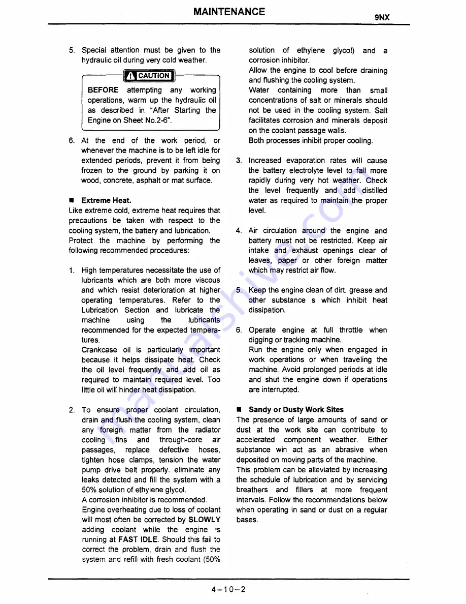
Page 96: ...ling system componentfound to be defective possibility keep the tank as full as is practical during cold weather This may entail refilling the tank more frequently than usual but the inconvenience is...

Page 97: ...mended Engine overheating due to loss of coolant will most often be corrected by SLOWLY adding coolant while the engine is running at FAST IDLE Should this fail to correct the problem drain and flush...

Page 98: ...deteriorating effects of salt moisture or both To protect exposed metallic surfaces wiring paint and other items keep them dry and well lubricated where salt or high humidity are encountered Follow t...

Page 99: ...ed part of the hydraulic cylinder piston rods Store the battery after move the negative terminal and covering it or dismounting the battery from the machine Lock the control levers and pedals with the...

Page 100: ...RH Boomswing Service Arm Swing Travel LH S e i c e Boom Hoist Arm In Swing Travel Relief Valve P2 Valve Location MR1 MR2 OR1 OR2 OR3 SW1 SW2 Swing Rel Valve SW SWING MOTOR MaintenanceStd MPa kgf an2 1...

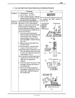
Page 101: ...pressure gauge to measure port on the control valve lnstall the fill plug 2 Measure the MRI Main relief valve Operation for Boom Bucket Travel R H and Service 1 Start the engine move the bucket or boo...

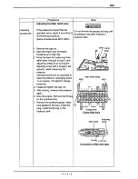
Page 102: ...hile measuringthe pressure Adjusting screw turn to clockwise to raise the pressure Adjusting screw 1 turn approx 100 kgf cm2change pressure 4 lnstall and tighten the cap nut 5 After locking measurethe...

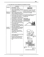
Page 103: ...bucket Pressure gauge to the ground 1 ngine off Relievetank pressure I UY installthe gauge pressure gauge to the arm IN line with hose adapter lnstall the fill plug Fig 1 2 2 Measure the over load rel...

Page 104: ...4 Install and tighten the nut 5 After locking measurethe pressure again 6 Lower the bucketto the ground Stop the engine Removethe fill plug on the hydraulictank 7 Removethe pressure gauge and hose ad...

Page 105: ...r structure with the track and engage the swing lock pin and lower the bucketto the ground 2 Stop the engine the fill plug on the hydraulictank lnstall the pressure gauge on the control valve to P2 ga...

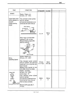
Page 106: ...Spool Stroke Control Valve 6 1 1 Swing Operating Speed Natural Drift 6 1 2 Travel Travel Speed Travel alignment Drift Time for Crowler belt 6 1 3 Boom Cylinder Speed 6 1 4 Arm Cylinder Speed 6 1 4 Buc...

Page 107: ...temp 50 60 C Measuring Position Use spring balance scale and CONTROL VALVE Boom 6 mrn C Arm Bucket Swing Stroke Stroke Travel Out Boom Swing 6 mrn t Blade CONDITION Engine Rated r p rn Oil temp 50 60...

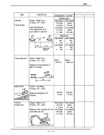
Page 108: ...Measure drift angle after 5...

Page 109: ...Level solid ground Time requiredfor 10 m travel after 5 m take off Measue turning distance x after 10 m travel Measuredrift gravity in 5 turns after one turn...

Page 110: ...Measure the variation of rod length in 10 minutes CONDITION Engine Rated r p m Oil temp 50 60 C Measure time for full extention or retractionof cylinder Engine Rated r p m Oil temp 50 60 C 1 STANDARD...

Reviews:

Related manuals for 9NX