This document is property of NIIGATA POWER SYSTEMS CO., LTD. It must be neither reproduced nor communicated nor published without permission.
SECTION
4
- DISASSEMBLY AND REASSEMBLY
4.5 GOVERNOR DRIVE AND FUEL CONTROL LINCAGE
4-5-03
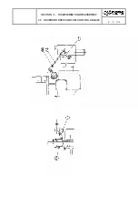
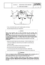
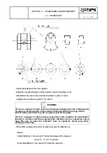
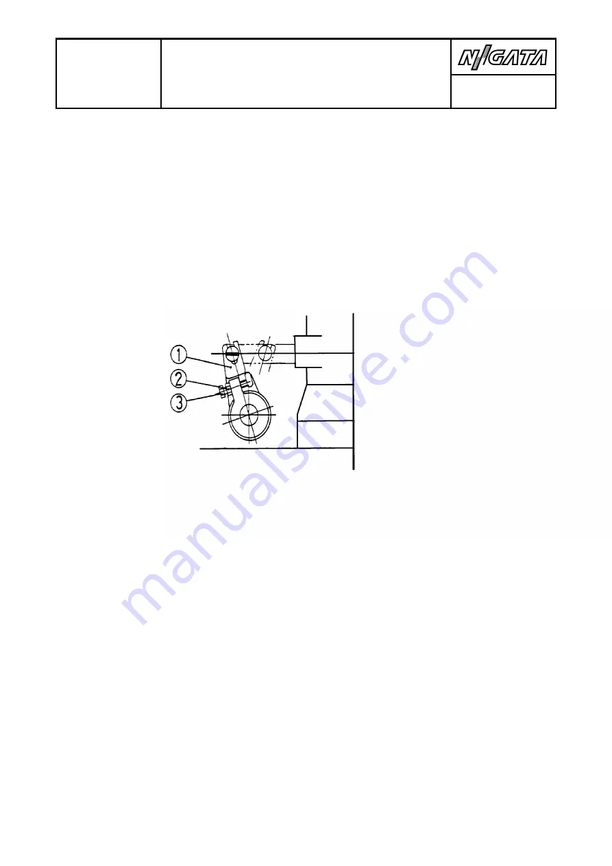
- After the pump has been mounted, connect the rack to the layshaft lever
①
.
- Move the governor control lever to the 'STOP' position.
- Loosen nut
②
and screw
③
.
- Set the injection pump rack to the '0' (zero) position, and tighten nut
②
.
- Recheck the stroke of the fuel pump rack by manually actuating the
lay shaft. Make certain that full rack stroke is obtained and that the
rack does not bind in any position.
4.5.5 Adjustment of governor control linkage
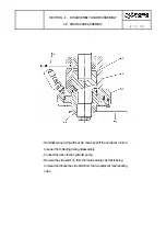
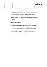
The governor is connected to the layshaft through two levers (bellcranks)
and a rod, as shown by following Figure. A return spring
④
is
attached to the lower bellcrank.
- Apply clean lube oil to each joint in the linkage.
- Operate the governor control lever by hand and make certain that the
linkage moves freely with no binding.
- Set the governor at the 'STOP' position and make certain that the
control lever indicator is at the "ZERO" position on the console scale.
If necessary, adjust the rod link
②
so that the marks align.
Summary of Contents for NIIGATA MG(L)26HLX
Page 2: ......
Page 34: ......
Page 38: ......
Page 40: ......
Page 60: ......
Page 66: ......
Page 68: ......
Page 80: ......
Page 82: ......
Page 86: ......
Page 88: ......
Page 94: ......
Page 107: ......
Page 108: ......
Page 110: ......
Page 130: ......
Page 132: ......
Page 170: ......
Page 174: ......
Page 186: ......
Page 188: ......
Page 192: ......


