background image

901176-00 NC

8

ihp.us.com

INSTALLATION


Continued

*  Purchase the optional equipment shutoff valve from your dealer�
**Minimum inlet pressure for purpose of input adjustment� 

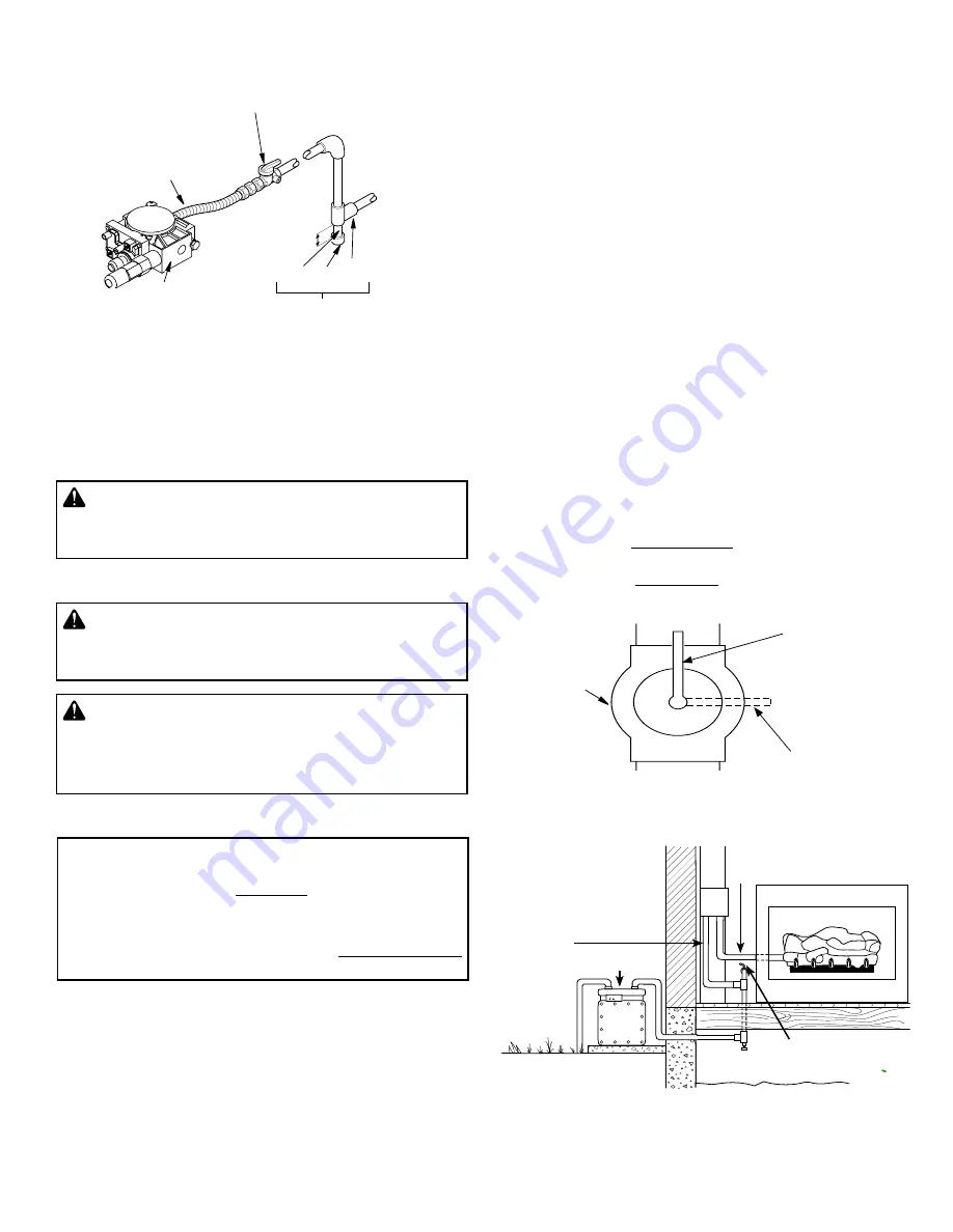
Figure B - Gas Connection

  Pipe  Cap Tee

 Nipple    Joint

Gas Control 

3" Minimum

Sediment Trap

Equipment Shutoff Valve 

With 1/8" NPT Tap*

Approved Flexible Gas 

Hose (if allowed by 

local codes)

NATURAL


From Gas 

Meter

(5" W�C�** 

to 10�5" W�C� 

Pressure)


CAUTION: Avoid damage to gas control. Hold gas 

control with wrench when connecting it to gas piping 

and/or fittings.


WARNING: Test all gas piping and connections, 

internal and external to unit, for leaks after installing 

or servicing. Correct all leaks at once.


WARNING: Never use an open flame to check for 

a leak. Apply a noncorrosive leak detection fluid to 

all joints. Bubbles forming show a leak. Correct all 

leaks at once.

Install in piping system between fuel supply and appliance� Locate 

sediment trap where trapped matter is not likely to freeze� A sediment 

trap traps moisture and contaminants� This keeps them from going 

into appliance controls� If sediment trap is not installed or is installed 

wrong, appliance may not run properly�

CHECKING GAS CONNECTIONS

PRESSURE TESTING GAS SUPPLY PIPING SYSTEM 

The appliance and its appliance main gas valve must be disconnected 

from the gas supply piping system during any pressure testing of 

that system at test pressures 

in excess of 

1/2 psi (3�5 kPa)�

The appliance must be isolated from the gas supply piping system 

by closing its equipment shutoff valve during any pressure testing of 

the gas supply piping system at test pressures 

equal to or less than


1/2 psi (3�5 kPa)�

Test Pressures In Excess Of 1/2 PSIG (3.5 kPa)

1�  Disconnect appliance with its appliance main gas valve (control 

valve) and equipment shutoff valve from gas supply piping system� 

Pressures in excess of 1/2 psig will damage appliance regulator�

2�  Cap off open end of gas pipe where equipment shutoff valve was 

connected�

3�  Pressurize supply piping system by opening main gas valve lo-

cated on or near gas meter for natural gas or using compressed 

air�

Test Pressures Equal To or Less Than 1/2 PSIG (3.5 kPa)

1�  Close equipment shutoff valve

 (see 

Figure C

).

2�  Pressurize supply piping system by opening main gas valve lo-

cated on or near gas meter for natural gas or using compressed 

air�

3�  Check all joints from gas meter to equipment shutoff valve for 

natural gas

.

 Apply noncorrosive leak detection fluid to all joints� 

Bubbles forming show a leak�

4�  Correct all leaks at once�

PRESSURE TESTING APPLIANCE GAS CONNECTIONS

1�  Open equipment shutoff valve 

(see 

Figure C

)

2�  Open main gas valve located on or near gas meter for natural gas�

3�  Make sure control knob of appliance is in the OFF position�

4�  Check all joints from gas meter to equipment shutoff valve for 

natural gas

Apply noncorrosive leak detection fluid to all joints� 

Bubbles forming show a leak� 

5�  Correct all leaks at once�

6�  Light appliance 

(see Remote Lighting, 

Page 11

)

� Check all other 

internal joints for leaks�

7�  Turn off appliance

 (see Shutting Down, 

Page 11

).

Figure C


- Equipment Shutoff Valve

Open

Closed

Equipment 

Shutoff 

Valve

4�  Check all joints of gas supply piping system� Apply noncorrosive 

leak detection fluid to all joints� Bubbles forming show a leak� 

5�  Correct all leaks at once�
6�  Reconnect appliance and equipment shutoff valve to gas supply� 

Check reconnected fittings for leaks� 

Figure D


- Checking Gas Joints (Natural Gas Only)

GAS ENTERS EIS FROM GAS 

METER 

GAS LEAVES EIS 

THROUGH FIREPLACE 

AND CONNECTS TO 

LOGSET

EIS

GAS METER 

GAS SHUTOFF VALVE 

Summary of Contents for DUALBURNER24N

Page 1: ...r call the fire department Installation and service must be performed by a qualified installer service agency or the gas supplier EIS Models DUALBURNER24N DUALBURNER30N DUALBURNER36N VTDEISKIT24N For...

Page 2: ...e fireplace IMPORTANT Read this owner s manual carefully and completelybeforetryingtoassemble operateorservice this appliance Improper use of this fireplace can cause seriousinjuryordeathfromburns fir...

Page 3: ...area of the appliance Toddlers young children and others may be susceptible to accidental burns A physical barrier is recommended if there are at risk individuals in the house To restrict accesstoafir...

Page 4: ...d burning fireplace or a UL 127 listed wood burning fireplace BOTH VTDEISKITN AND DUALBURNER ARE REQUIRED TO COMPLETE THIS SYSTEM IN ORDER TO SATISFY THE Z21 60 STANDARD FOR USE WITH NATURAL GAS ONLY...

Page 5: ...ER CLAMP ACCESSORY FOR VENTED OPERATION NOTE Appliance must be installed only in a solid fuel burning fire place with a working flue and constructed of noncombustible material This unit may not be ins...

Page 6: ...10 fee Chart shows mainimum opening sq in for the given height and input rate Column marked Max input corresponds to the maximum allowable input rate kBTU hr for the given height For Masonry Built Fi...

Page 7: ...regulator WARNING A qualified service person must con nect appliance to gas supply Follow all local codes CONNECTING TO GAS SUPPLY WARNING Never connect this appliance to private non utility gas well...

Page 8: ...Pa 1 Disconnect appliance with its appliance main gas valve control valve and equipment shutoff valve from gas supply piping system Pressures in excess of 1 2 psig will damage appliance regulator 2 Ca...

Page 9: ...NWHITEBIRCH36 OZARKCHARREDOAK36 SMOKYWEATHEREDOAK36 LOG MEDIA PLACEMENT It is very important to install these logs exactly as instructed Do not modify logs Please refer to specific Log Placement Guide...

Page 10: ...valve is installed on either the gas in or gas out side of the valve It is recommended to hard pipe in the connections with unions installed inside the box Gas In Gas Out PILOT INSTALLATION Un coil th...

Page 11: ...the remote does not function and batteries with an adequate power level are installed refer to the TRANSMITTER FUNCTION section Note Step 1 may not be required if previously done during an earlier li...

Page 12: ...st dirt lint and pet hair Clean these air inlet holes prior to each heating season Blocked air holes will create soot We recommend that you clean the unit every three months during operation and have...

Page 13: ...o the manufacturers recommendations and the below wiring diagram It is the job of the electrician to read the wiring diagram according to RoberShaw specifications CAUTION Label all wires prior to disc...

Page 14: ...ccept the transmitter security code be sure the slide button on the receiver is in the REMOTE position the receiver will not LEARN if the slide switch is in the ON or OFF position The LEARN button in...

Page 15: ...NG Turn off appliance and let cool before servicing Only a qualified service person should service and repair appliance TROUBLESHOOTING NOTE All troubleshooting items are listed in order of operation...

Page 16: ...furnace chassis 4 Flame rectification signal from pilot to ignition control unit weak 5 Faulty ignition control unit 1 Replace components 2 Replace components 3 Verify wiring 4 Verify wiring 5 Replace...

Page 17: ...on or application of this appliance please contact your dealer IHP 1769 East Lawrence Street Russellville AL 35654 Visit us at ihp us com SERVICE HINTS When Gas Pressure Is Too Low pilot will not stay...

Page 18: ...ALBURNER36N Cat No Model F4742 DUALBURNER24N F4746 DUALBURNER30N F4750 DUALBURNER36N WARNING Failure to position the parts in accordance with these diagrams or failure to use only parts specifi cally...

Page 19: ...tructions listed under Replacement Parts on Page 20 of this manual CAT NO MODEL DESCRIPTION F4739 ASHTONWHITEBIRCH24 24 ASHTON WHITE BIRCH LOGS 7 PCS SET F4740 ASHTONWHITEBIRCH30 30 ASHTON WHITE BIRCH...

Page 20: ...___________________________ ______________________________________________________ ______________________________________________________ ______________________________________________________ _______...

Page 21: ...ce with the instructions provided with the Product d damages repairs or inefficiency resulting from faulty installation or application of the Product This Limited Three Year Warranty covers only parts...

Page 22: ...nce serial number Date appliance was Installed Type of gas appliance uses Dealer name Innovative Hearth Products IHP reserves the right to make changes at any time without notice in design materials s...

Reviews: