INNOVATIVE
HEARTH PRODUCTS • KITS AND ACCESSORIES • BLOWER KIT (MODELS FBK-100 AND FBK-200)
4
NOTE: DIAGRAMS AND ILLUSTRATIONS NOT TO SCALE
ELITE LINEAR DIRECT-VENT GAS FIREPLACES
WARNING/AVERTISSEMENT
Burn hazard.
Risque de brûlure.
•
Install only when fireplace is OFF and COLD.
•
Installer seulement lorsque le foyer est ÉTEINT et FROID.
1.
Shut OFF the gas supply to the appliance.
2.
Disconnect the power supply at the circuit breaker.
NOTE:
Make sure the appliance is COLD before starting
installation.
3.
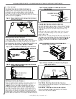
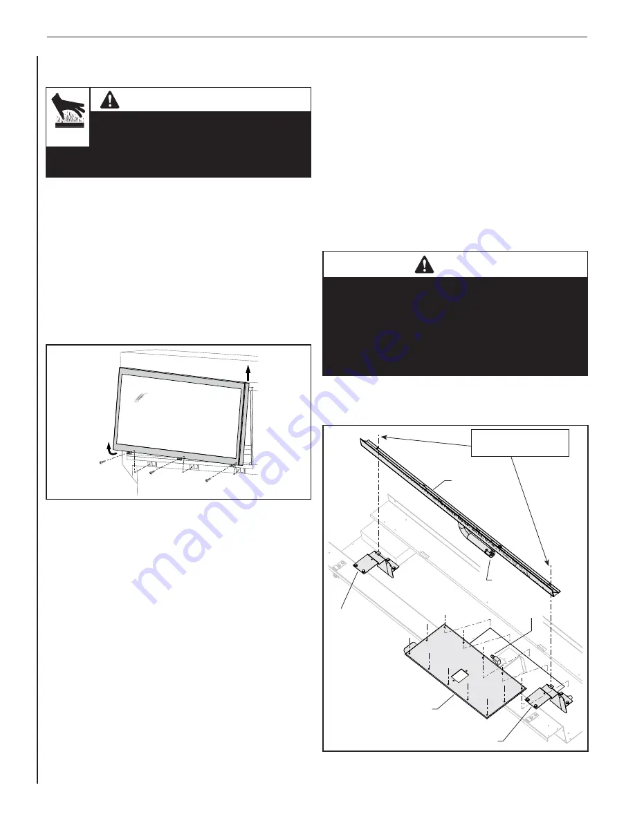
Remove the glass door by removing the three (3) screws
securing the lower edge of the door to the fireplace (
Figure 15
).
Grasp the door assembly by the side edges, swing out the lower
edge, and then lift up to unhook it from the fireplace, taking care
not to damage the glass. Set aside screws and door assembly
in a secure location for later reinstallation.
Figure 9: Removing the Glass Door
Glass Door Assembly
4.
Remove the media.
NOTE:
Glass media can be removed using a clean, dry,
empty shop vac. For all other types of media, follow the
instructions provided with the Media Kit.
5.
Remove the fireplace floor, by removing the six (6) 5/16 in.
screws securing it.
6.
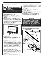
Remove the burner assembly with attached air shutter
assembly, by removing the two (2) 5/16 in. screws securing
the burner to the burner brackets (
Figure 16
). Carefully slide
the burner to the left, to clear the venturi from the orifice
(
Figure 17
). Rotate the burner to release the air shutter
adjustment rod from the air shutter lever (
Figure 17
). Set
aside the screws and burner assembly in a secure location
for later reinstallation.
7.
Remove the control compartment access door and gasket
(
Figure 16
), by removing the twelve (12) screws. Set the
door and screws aside for later reinstallation.
8.
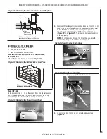
Position the blower assembly so the tabs (on the cabinet
base) are seated in the notches of the blower bracket. Bend
the tabs over to secure the blower assembly. Reinstall
the blower shield with the blower cord routed to the
electrical outlet.
9.
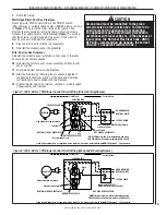
Route a 3-wire, 120 Vac power line to the ON/OFF switch
(FBK-100 kits) or variable speed control (FBK-200 kits) as
shown in
Figure 7
. Then route the wires to the fireplace
junction box. Remove the receptacle by removing the two (2)
securing screws. Connect the supply wires to the receptacle
(
Figure 7
), ensuring that the polarity (as determined by
the colors of the wires) is exactly as shown. Reinstall
the receptacle.
10.
Plug the blower cord into the switched (black wire)
receptacle (
Figure 7
).
11.
Confirm blower operation (startup, shutdown, variable speed
[if applicable], and running).
12.
Replace all removed components, as applicable (control
compartment access door and gasket, burner assembly
with attached air shutter assembly, media, glass door, and
modesty panel).
CAUTION
Ground lead must be connected to the green
screw located on the junction box. Failure to do
so will prevent the appliance from operating.
The appliance must be electrically grounded in
accordance with local codes or, in the absence of
local codes, the National Electrical Code, ANSI/
NFPA 70—latest edition (In Canada, the current
CSA C22-1 Canadian Electrical Code.)
Figure 10: Accessing the Control Compartment on Elite
Linear Fireplaces
Control Compartment
Access Door and Gasket
Right Burner Bracket
Remove two screws to
remove burner assembly.
Burner
Assembly
Left Burner
Bracket
Venturi
Burner
Orifice


