NOTE: DIAGRAMS & ILLUSTRATIONS ARE NOT TO SCALE
1
SECURE FLEX
®
VENT KIT
(12’ COMPRESSED LENGTH)
HEARTH PRODUCTS
KITS AND ACCESSORIES
INSTALLATION INSTRUCTIONS FOR SECURE FLEX
®
VENT KIT (MODEL NO. SF-12) (CATALOG NO. 98K03)
USED WITH DIRECT-VENT GAS FIREPLACES IN HORIZONTAL VENTING APPLICATIONS ONLY
GENERAL APPLICATIONS
Refer to the fireplace installation instructions for approved horizontal vent-
ing configurations. Rigid Secure Vent
®
(SV4.5) direct-vent components
are shown in these configurations; however, these Secure Flex vent kits
may also be used. All restrictions, clearances and allowances that pertain
to the rigid piping apply to the flexible venting also.
Expanding Secure Flex and Secure Flex Joining Restrictions -
Flexible vent pipe is packaged and shipped in its contracted state. When
installing flexible vent pipe, its length may be expanded up to twice its
contracted size. This 12’ section of flexible pipe may be expanded up
to 24’. The 12’ section may be cut to any length to suit a particular ap-
plication; however,
the flex sections must not be joined together
to extend a vent run.
After expanding the vent, check that the vent’s
spring spacers are spaced every 12” or less.
Adding Secure Flex to the End of a Secure Vent (Rigid Vent) Run -
Secure Flex may be added to the end of a vent run made up of rigid
Secure Vent (SV4.5) vent sections. The flex adaptor (87L00) must be used
when connecting the flexible pipe to the rigid . All the restrictions such as
venting length, height, routing, horizontal to vertical ratio requirements or
clearance considerations as detailed in the fireplace installation instructions
for rigid vent must be adhered to for the flexible vent.
Attaching the Flexible Vent to the Adaptor
(See parts A and B below
and Figure 2)
-
A. Install the Inner Flex Pipe -
1. Install the small gear clamp loosely around the inner flexible vent
pipe, push it back out of the way.
2. Apply a bead of Mill-Pac Black (700°F) high temperature sealant -
Catalog No. 10K81) to the inner adaptor collar, approximately 1/2”
from the end.
3. Pull and extend the inner flexible vent pipe.
4. Slide the inner flex pipe over the adaptor collar. Overlap the flexible
vent pipe with the adaptor collar 1-3/4", ensuring that flexible vent
pipe is free from damage or tears.
5. Slide the gear clamp down to approximately 3/4” from the end of
the flexible pipe. Tighten the clamp fully to secure the flexible pipe
to the inner adaptor collar.
6. Install three screws 120 degrees apart through the flexible vent
pipe and into the adaptor collar just below the gear clamp to provide
additional security to the connection.
GENERAL INFORMATION
This Secure Flex
®
venting kit may be used when horizontally venting an
IHP direct-vent gas fireplace. It contains 12’ of compressed flex vent.
If you encounter any problems, need clarification of these instructions or
are not qualified to properly install this kit, contact you local distributor
or dealer.
Read this instruction sheet in its entirety before beginning the installation.
ALL WARNINGS AND PRECAUTIONS IN THE INSTALLATION AND
OPERATION MANUALS PROVIDED WITH THE APPLIANCE APPLY TO
THESE INSTRUCTIONS.
INSTALLATION INSTRUCTIONS
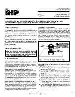
Figure 1 - Connecting Flex Adaptor To Appliance Collar
750053M
Rev. B 05/2014
Installation of Secure Flex
®
Adaptor -
Secure Flex comes with an adaptor (catalog no. 87L00) that can be fitted
to the appliance collar or the inclined channel end of the last Secure Vent
section (SV4.5) in a rigid system. Align the dimpled end of the adaptor
over the previously installed section or appliance collar, adjusting the
radial alignment until the four locking dimples of the adaptor are aligned
with the inlets of the four incline channels of the last vent section or
collar. Push on the adaptor until it fully engages, then twist the adaptor
clockwise running the dimples down and along the incline channels until
they seat at the end of the channels.
See Figure 1
.
Flex
Adaptor
Align the dimple (four places)
with the opening of the locking
incline channel on appliance
collar. Twist vent component
clockwise to engage and seal.
Locking
Incline Channel
DR
AF
T
4/1
5/2
01
4
INSTALLATION SHOULD BE PERFORMED BY A qUALIFIED
TECHNICIAN ACCORDING TO THESE INSTRUCTIONS, THE
INSTALLATION INSTRUCTIONS FOR THE PARTICULAR AP-
PLIANCE BEING INSTALLED, AND LOCAL CODES.


