127160-01B
5
IHP.us.com
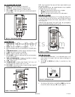
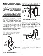
SETTING TEMPERATURE SWING (Temperature differential)
The Thermo Mode on the transmitter operates the appliance whenever
the room temperature varies a certain number of degrees from the set
temperature. This variation is called the “SWING” or TEMPERATURE
DIFFERENTIAL. The factory preset swing temperature is 2 ºF (1 ºC). To
change the “Swing Setting:”
•
Press the SET button and the DOWN touch button simultaneously
to display the current “swing” setting in the set temp frame. The
letter “S” will display in the room temp frame on the LCD screen.
•
Press the UP or DOWN touch button to adjust the “SWING” tem-
perature (1º-3º F) (1º-2º C).
•
To store the “swing” setting press the SET button, and the new
“swing” setting will be automatically programmed.
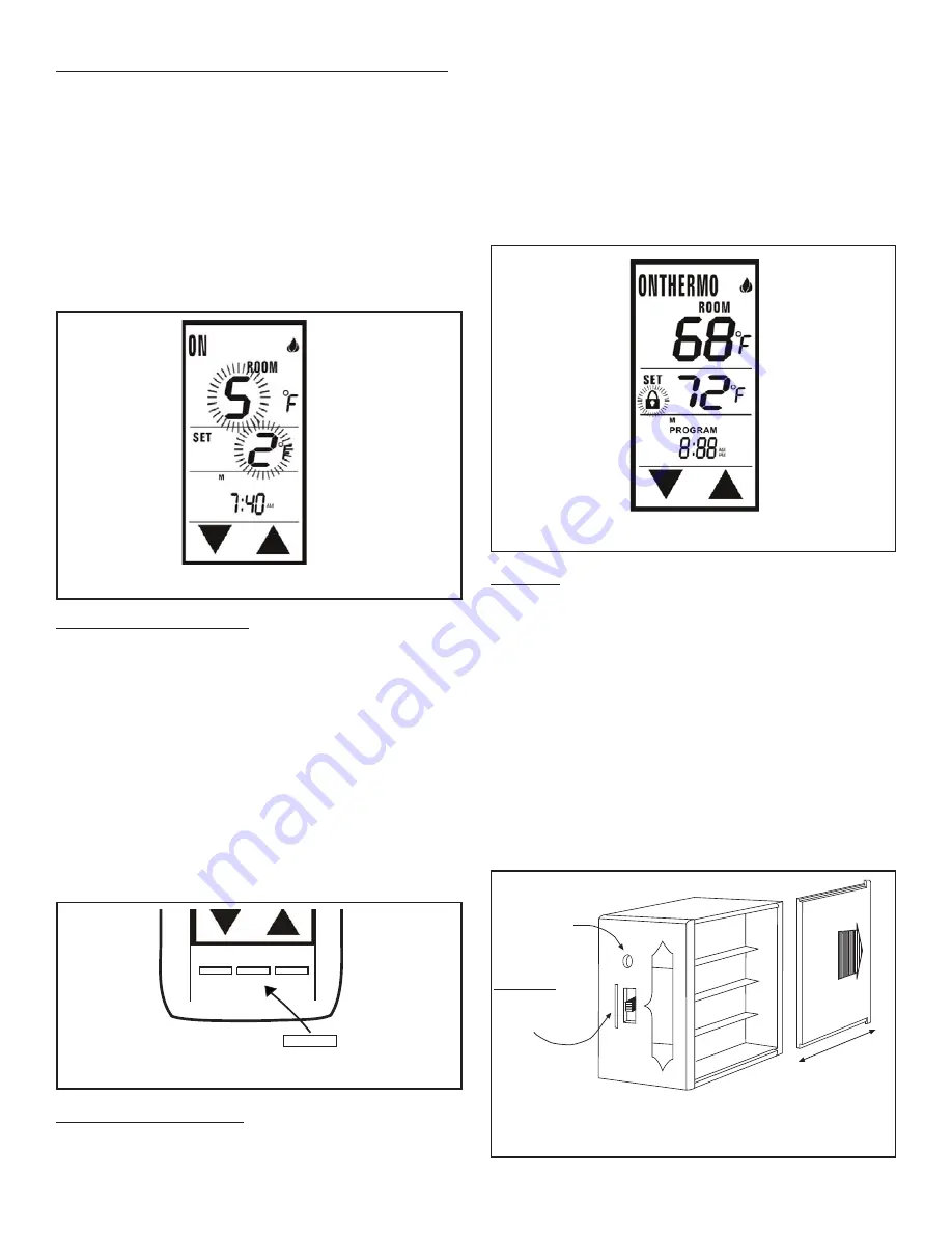
RECEIVER
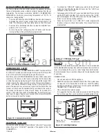
Install the 4 AA-size batteries supplied with the unit. It is recommended
that ALKALINE batteries always be used for this product. Be sure the bat-
teries are installed with the (+) and (-) ends facing the correct direction.
The remote receiver has a 3-position slide switch for selecting the mode
of operation.
ON/REMOTE/OFF
•
ON: will manually turn ON the appliance.
•
REMOTE: will allow use of handheld transmitter. If the system does
not respond to the transmitter on initial use, check the battery
positions in the remote. If that does not work, see the LEARNING
TRANSMITTER TO RECEIVER section.
•
OFF: will disable the remote receiver.
•
It is suggested that the slide switch be placed in the OFF position
if you will be away from your home for an extended period of time.
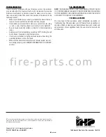
COMMUNICATION - SAFETY
This remote control has a COMMUNICATION –SAFETY function built into
its software. It provides an extra margin of safety when the Transmitter
is out of the normal 20-foot operating range of the receiver.
At all times and in all OPERATING MODES, the transmitter sends an RF
signal every 15 minutes, to the receiver, indicating that the transmitter
is within the normal operating range of 20 feet. Should the receiver NOT
receive a transmitter signal every 15 minutes, the receiver will begin a
2-hour (120 minute) countdown timing function. If during this 2-hour
period, the receiver does not receive a signal from the transmitter, the
receiver will shut down the appliance being controlled by the receiver.
The receiver will then emit a series of rapid “beeps” for a period of 10
seconds. Then after 10 seconds of rapid beeping, the receiver will con-
tinue to emit a single “beep” every 4 seconds until a transmitter MODE
button is pressed to reset the receiver.
Figure 15 - Setting Temperature Swing
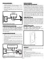
•
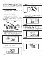
To activate the “LOCK-OUT” feature, press and hold the UP touch
button and the SET button together for 5 seconds. The “LOCK” icon
will appear on the LCD screen.
•
To disengage the “LOCK-OUT”, press and hold the UP touch button
and the SET button together for 5 seconds or more, the “LOCK”
icon will disappear from the LCD screen and the transmitter will
return to its normal operating condition.
•
When the Transmitter is in “LOCK-OUT” mode, programmed
functions will go on without interruption; Only manual functions
are prevented.
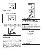
Figure 16 - Communication-Safety
MODE
MODE
SET
PROG
Figure 17 - Childproof ''Lock-out''
REMOTE
N
O
OFF
LEARN
Requires 4-AA 1.5V
alkaline batteries
Learning
button
Remote Receiver
Battery co
ver slides on/off
Slide
Switch
ON
REMOTE
OFF
Figure 18 - Installing Batteries
CHILDPROOF ''LOCK-OUT''
This remote control includes a CHILDPROOF “LOCK-OUT” feature that
allows the user to “LOCK-OUT” operation of the appliance from the
TRANSMITTER.
f i r e - p a r t s . c o m


