474-Add-on Modules
Description
13
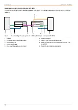
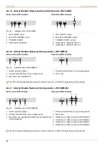
An add-on module can contain up to 2 independent function parts (part A and B), one on the left and one on the right,
see Fig. 1.
Fig. 1
KVM Extender pair with CPU Unit and CON Unit
1 KVM Extender pair
2 Add-on module/USB 2.0 stand-alone module (optional)
3 Extender module
4 Part A of the CPU add-on module (optional)
5 Part B of the CPU add-on module (optional)
6 Chassis
7 CPU Unit
8 Interconnect cable
9 CON Unit
10 Part A of the CON add-on module (optional)
11 Part B of the CON add-on module (optional)
12 Chassis
13 Extender module
14 Add-on module/USB 2.0 stand-alone module (optional)
4.1.3 Embedded Signals
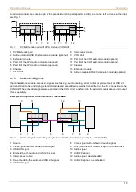
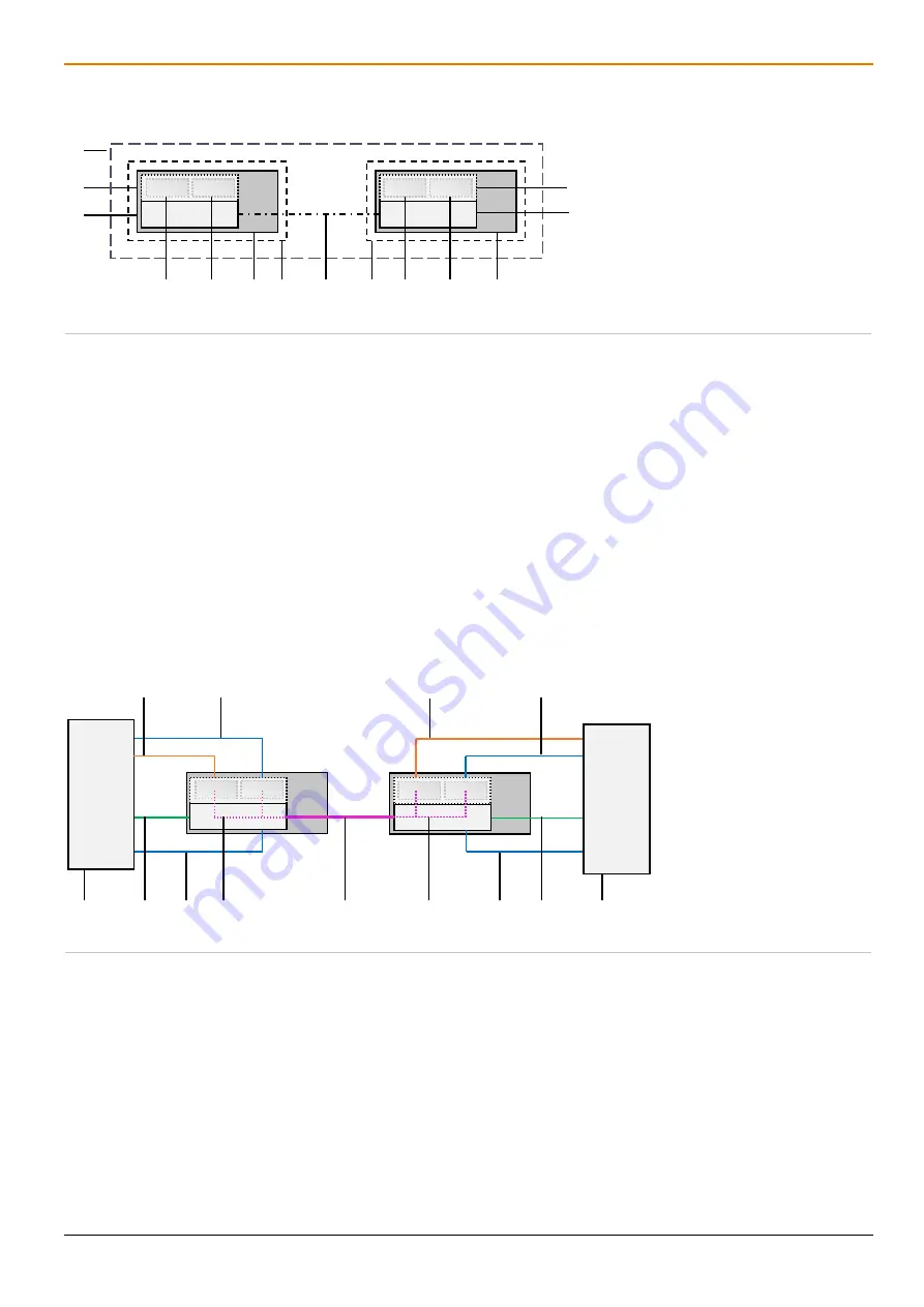
If optional add-on modules are used, signals such as e.g., audio (analog, serial, digital or symmetrical) or USB 2.0
are transferred to the underlying extender module and embedded as well as transmitted via the link connection to the
CON Unit. The embedded signals are extracted in the CON Unit, transferred to the add-on module above and output
there separately.
Example with optional Add-on Module L- /R474-BAE
Fig. 2
Embedding/de-embedding of signals in a KVM extender pair (example L- /R474-BAE)
1 Source
2 Video signal with embedded audio signal
3 USB HID signal
4 Embedding the audio and USB 2.0 signal
5 Interconnect cable
6 De-embedding the audio and USB 2.0 signal
7 USB HID signal
8 Video signal with embedded audio signal
9 Sink (console with monitor, keyboard, and mouse)
10 Audio signal
11 USB 2.0 signal
12 Audio signal, de-embedded
13 USB 2.0 signal, de-embedded
1
2
3
14
13
6 7
12
9
4
5
10
11
8
5
10
11
4
2
3
1
12
13
6
7
9
8


