background image

Installation and Setup 

474-Add-on Modules


42 

6.6  Connecting Add-on Module PS/2 

1.  Connect the source to the PS/2 ports of the CPU Unit. 
2.  Connect the PS/2 devices to the PS/2 ports of the CON Unit. 


6.7  Connecting Add-on Module USB 2.0 embedded 

1.  Connect the source to the USB 2.0 port of the CPU Unit. 
2.  Connect the USB 2.0 devices to the USB 2.0 ports of the CON Unit. 


6.8  Connecting Add-on Module USB 2.0 

1.  Connect the source to the USB 2.0 ports of the CPU Unit. 
2.  Connect the USB 2.0 devices to the USB 2.0 ports of the CON Unit. 


6.9  Connecting Add-on Module GPIO 

The GPIO add-on modules R474-BGX or R474-BGE2 are configured via DIP switches. In the delivery state, all DIP 
switches are set to the bottom (input). 
The DIP switches belong to the pins listed below: 


Pin 1 

Pin2 

Pin 3 

Pin 4 

Pin 5 

Pin 6 

Pin 7 

Pin 8 

Pin 9 

DIP Switch 


There are two options to use the GPIO add-on module depending on the DIP switch positions: 

  output interface for LED connection for MSC (Multi Screen Control) (5 V, 137 mA per channel) 

  input interface for push button connection (Macros, Favorites, Keys) 


Option 1 - LED Output Interface for MSC (Multi Screen Control) 

All DIP switches must be set to upper position. The settings for the GPIO add-on module in the CON Device settings 
(matrix configuration) have to be set as “MSC Switch (default)” to indicate the active console (mouse position) by a 
LED. Please refer to the Draco tera matrix user manual. 


Fig. 45 

Example - GPIO add-on module set as output interface 


Summary of Contents for Draco vario 474 Series

Page 1: ...Document 474 Add on Modules_REV01 00_en Edition 2022 08 19 USER MANUAL Draco vario Add on Modules Series 474 ...

Page 2: ...odels are clearly described Please note the change log for this manual in chapter 15 page 77 The manufacturer reserves the right to change specifications functions or circuitry of the Serie described here without notice Information in this manual can be changed expanded or deleted without notice You can find the current version of the manual in the download area of our website Copyright 2022 All r...

Page 3: ... on Modules 18 4 3 2 USB 2 0 Stand alone Modules 20 4 3 3 Fan Cartridge Module 20 4 4 Accessories 20 4 5 Scope of Delivery 21 4 6 Product View 22 4 6 1 Add on Module USB 2 0 embedded L R474 BXE 22 4 6 2 Add on Module USB 2 0 embedded L R474 BXE2 22 4 6 3 Add on Module USB HID L R474 BXH 22 4 6 4 Add on Module Analog Audio bidirectional L R474 BAX BRX 23 4 6 5 Add on Module Analog Audio bidirection...

Page 4: ...d on Module USB HID 35 4 7 4 Add on Module USB 2 0 embedded L R474 BXE 36 4 7 5 Add on Modules USB 2 0 embedded L R474 BXE2 37 4 7 6 USB 2 0 Stand alone Modules 38 4 7 7 Fan Cartridge Module 39 5 Access Options 40 6 Installation and Setup 41 6 1 Connecting Add on Module Analog Audio Serial RS232 41 6 2 Connecting Add on Module Analog Audio Serial RS422 41 6 3 Connecting Add on Module Digital Audio...

Page 5: ... Data 55 10 1 Interfaces 55 10 1 1 Mini USB 55 10 1 2 USB HID 55 10 1 3 PS 2 55 10 1 4 USB 2 0 transparent 56 10 1 5 GPIO 56 10 1 6 RS232 Serial 56 10 1 7 RS422 Serial 57 10 1 8 Analog Audio 58 10 1 9 Digital Audio 59 10 1 10 Balanced Audio 60 10 2 Interconnect Cables 62 10 2 1 Cat X 62 10 2 2 Fiber 63 10 3 Connector Pinouts 64 10 3 1 USB Type A 64 10 3 2 Mini USB Type B 64 10 3 3 PS 2 64 10 3 4 D...

Page 6: ... 1 Add on Modules 68 10 6 2 USB 2 0 Stand alone Modules 68 10 6 3 Fan Cartridge Module 68 10 7 Environmental Conditions and Emissions 68 10 8 MTBF 68 11 Technical Support 69 11 1 Support Checklist 69 11 2 Shipping Checklist 69 12 Glossary 70 13 Index 72 14 Table of Figures 75 15 Change Log 77 ...

Page 7: ...he Functionality of your device or the security of your data This symbol indicates instructions for procedures recommended by the manufacturer for an effective utilization of the device potential This symbol indicates information about special features on the device or when using device and Function variants 1 3 Terms and Spellings Uniform terms and spellings are used in this manual for better rea...

Page 8: ...e transferred via interconnection between extender modules CPU Units and CON Units USB 2 0 Stand alone Modules USB 2 0 stand alone modules are used to increase the distance between sources and associated consoles The transmission range of USB 2 0 data can be extended using Cat X cables or fiber optic cables USB 2 0 stand alone modules with Cat X connections are unsuitable for connection between bu...

Page 9: ...ration of this equipment in a residential area is likely to cause harmful interference in which case the user will be required to correct the interference at his own expense Changes or modifications not expressly approved by the party responsible for compliance could void the user s authority to operate the equipment Shielded cables must be used with this equipment to maintain compliance with radi...

Page 10: ...al injury damage to the device or endanger the security of your data Take any required ESD precautions Installation Location While operating the device can get warm Damage to the device can occur in a damp environment Use the device only in dry indoor environments Use the device only in a room with adequate ventilation Place the device at a sufficient distance from the operator Connection Check th...

Page 11: ...écharges électrostatiques Emplacement de l installation Pendant le fonctionnement le périphérique peut chauffer Le périphérique peut être endommagé dans un environnement humide N utilisez le périphérique que dans un environnement sec et intérieur N utilisez le périphérique dans un lieu correctement ventilée Placez le périphérique à une distance suffisante de l opérateur Connexion Avant de connecte...

Page 12: ...or more information please refer to the manual 474 BODY Described in this manual For more information please refer to the respective extender module manual 4 1 2 System Structure and Terms A KVM pair consists of 2 KVM extender modules each with at least one CPU extender module and at least one CON extender module The various extender modules are installed respectively in a Draco vario chassis 2 sl...

Page 13: ...s such as e g audio analog serial digital or symmetrical or USB 2 0 are transferred to the underlying extender module and embedded as well as transmitted via the link connection to the CON Unit The embedded signals are extracted in the CON Unit transferred to the add on module above and output there separately Example with optional Add on Module L R474 BAE Fig 2 Embedding de embedding of signals i...

Page 14: ...r the CON Unit required Fig 3 De embedding of audio signals in a KVM extender pair example R474 BDX 1 Source 2 Video signal with embedded audio 3 USB HID signal 4 Interconnect cable 5 De embedding digital audio signal 6 USB HID signal 7 Video signal with embedded audio 8 Sink console with monitor keyboard mouse and speakers 9 De embedded digital audio signal 4 2 3 1 9 5 6 8 7 ...

Page 15: ...474 Add on Modules Description 15 4 1 4 Overview Add on Modules This section illustrates an overview of the available types of add on modules for KVM extender modules Fig 4 Overview add on modules ...

Page 16: ...Audio compatibility of extender modules and add on modules Extender modules of HDMI 1 3 Serie 481 491 and DP 1 1 Serie 483 493 support 5 1 channel digital audio whereas extender modules of HDMI 2 0 Serie 495 and DP 1 2 Serie 490 only support 2 channels Requires an audio add on module on the CPU Unit or the CON Unit True embedded audio Connection is representing audio content only Analog audio add ...

Page 17: ... Fig 6 Installation example Single Head with add on module audio 1 Source 2 CPU Unit 3 Interconnect cable 4 CON Unit 5 Console monitor keyboard mouse 6 Audio sink optional only with devices with add on module analog audio Serial option digital audio or balanced analog audio 4 2 2 Dual Head Installation with Add on Module USB 2 0 Fig 7 Installation example Dual Head with add on module USB 2 0 1 Sou...

Page 18: ... bidirectional RS232 serial and 2x USB 2 0 embedded up to 36 Mbit s R474 BAE L474 BAE2 Add on module with analog audio bidirectional RS232 serial and 4x USB 2 0 embedded up to 50 100 Mbit s R474 BAE2 L474 BAH Add on module with analog audio bidirectional RS232 serial and 2x USB HID Hot Key function available R474 BAH R474 BAH L474 BAP Add on module with analog audio bidirectional RS232 serial and ...

Page 19: ...d 2x USB 2 0 embedded up to 36 Mbit s R474 BDE L474 BDE2 Add on module with digital audio unidirectional and 4x USB 2 0 embedded up to 50 100 Mbit s R474 BDE2 L474 BDH Add on module with digital audio unidirectional and 2x USB HID Hot Key function available R474 BDH R474 BDH L474 BDA Add on module with digital audio unidirectional analog audio bidirectional and RS232 R474 BDA L474 BDD Add on modul...

Page 20: ...p to 480 Mbit s Single Mode Fiber Base ICRON 2300 Core R474 BXUS 4 3 3 Fan Cartridge Module Part No Description 474 MODFAN Fan cartridge module retrofittable for all Draco vario chassis 4 4 Accessories Part No Description Interface 455 CK Duplex audio cable 2 m 3 5 mm Audio 455 CR Cinch cable 2 5 m Audio 455 CT TOSLINK cable 2 0 m Audio 247 U1 USB cable Type A B 1 8 m USB USB HID 247 U2 USB cable ...

Page 21: ... g 2 audio parts or 1 audio part and 1 PS 2 part Product type Delivery scope per function part Add on module USB 2 0 USB 2 0 embedded USB cable Type A B 1 8 m Add on module USB HID USB cable Type A B 1 8 m Add on module analog audio Serial 1x Serial cable 1 8 m RS232 1x Duplex audio cable 2 m 3 5 mm Add on module digital audio 1x Cinch cable 2 5 m 1x TOSLINK cable 2 0 m Add on module PS 2 2x PS 2 ...

Page 22: ...edded L R474 BXE2 Source side CPU module Sink side CON module Fig 9 Interface side L R474 BXE2 1 USB Type B USB 2 0 up to 50 100 Mbit s 1 USB Type A USB 2 0 up to 50 100 Mbit s 2 USB Type A USB 2 0 up to 50 100 Mbit s 3 USB Type A USB 2 0 up to 50 100 Mbit s 4 USB Type A USB 2 0 up to 50 100 Mbit s 4 6 3 Add on Module USB HID L R474 BXH Source side CPU module Sink side CON module Fig 10 Interface ...

Page 23: ...tput 4 USB Type B USB 2 0 up to 36 Mbit s 1 D Sub 9 male socket RS232 serial 2 3 5 mm jack socket analog audio input 3 3 5 mm jack socket analog audio output 4 USB Type A USB 2 0 up to 36 Mbit s 5 USB Type A USB 2 0 up to 36 Mbit s 4 6 6 Add on Module Analog Audio bidirectional L R474 BAE2 BRE2 Source side CPU module Sink side CON module Fig 13 Interface side L R474 BAE2 BRE2 1 D Sub 9 female sock...

Page 24: ... module Fig 15 Interface side L R474 BAP 1 D Sub 9 female socket RS232 serial 2 3 5 mm jack socket analog audio input 3 3 5 mm jack socket analog audio output 4 PS 2 output mouse 5 PS 2 output keyboard 1 D Sub 9 male socket RS232 serial 2 3 5 mm jack socket analog audio input 3 3 5 mm jack socket analog audio output 4 PS 2 input mouse 5 PS 2 input keyboard 4 6 9 Add on Module Analog Audio bidirect...

Page 25: ... Sub 9 female socket RS422 serial 2 3 5 mm jack socket analog audio input 3 3 5 mm jack socket analog audio output 4 USB Type B USB 2 0 up to 36 Mbit s 1 D Sub 9 male socket RS422 serial 2 3 5 mm jack socket analog audio input 3 3 5 mm jack socket analog audio output 4 USB Type A USB 2 0 up to 36 Mbit s 5 USB Type A USB 2 0 up to 36 Mbit s 4 6 12 Add on Module Analog Audio bidirectional L R474 BSE...

Page 26: ...al Audio unidirectional L R474 BDX Source side CPU module Sink side CON module Fig 21 Interface side L R474 BDX 1 RCA S PDIF input 2 Mini XLR AES EBU input 3 TOSLINK S PDIF input 1 RCA S PDIF output 2 Mini XLR AES EBU output 3 TOSLINK S PDIF output 4 6 15 Add on Module Digital Audio unidirectional L R474 BDD Source side CPU module Sink side CON module Fig 22 Interface side L R474 BDD 1 RCA S PDIF ...

Page 27: ...ide CON module Fig 24 Interface side L R474 BDE 1 RCA S PDIF input 2 Mini XLR AES EBU input 3 TOSLINK S PDIF input 4 USB Type B USB 2 0 up to 36 Mbit s 1 RCA S PDIF output 2 Mini XLR AES EBU output 3 TOSLINK S PDIF output 4 USB Type A USB 2 0 up to 36 Mbit s 5 USB Type A USB 2 0 up to 36 Mbit s 4 6 18 Add on Module Digital Audio unidirectional L R474 BDE2 Source side CPU module Sink side CON modul...

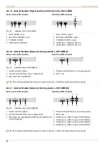
Page 28: ... pre amplification 1 Phoenix terminal block 6 pin analog audio 2 Not in use The CPU module with balanced audio can also be used on a CON Unit depending on the purpose 4 6 21 Add on Module Balanced Analog Audio L R474 BB2E2 Source side CPU module Sink side CON module Fig 28 Interface side L R474 BB2E2 1 Switch phantom power 2 Phoenix terminal block 6 pin analog audio 3 Dip switch pre amplification ...

Page 29: ...dd on Module Balanced Audio L R474 BBE2 Discontinued and no longer available since 01 2022 Source side CPU module Sink side CON module Fig 30 Interface side L R474 BBE2 1 Switch for phantom power 2 6 35 mm jack socket analog audio input 1 3 6 35 mm jack socket analog audio input 2 4 Dip switch for pre amplification 1 USB Type B USB 2 0 up to 50 100 Mbit s 1 6 35 mm jack socket analog audio output ...

Page 30: ...GPIO for an external switching solution via dry contact 2 D Sub 9 male socket RS232 serial 3 3 5 mm jack socket analog audio input 4 3 5 mm jack socket analog audio output 4 6 26 Add on Module GPIO R474 BGE2 Source side CPU module Fig 33 Interface side R474 BGE2 1 D Sub 9 male socket in output GPIO for an external switching solution via dry contact 2 USB Type A USB 2 0 up to 50 100 Mbit s 3 USB Ty...

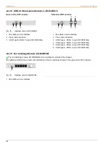
Page 31: ...ide L R474 BXUC 1 Mini USB service interface 2 Cat X interconnection 3 USB Type B USB 2 0 up to 50 100 Mbit s 1 Mini USB service interface 2 Cat X interconnection 3 USB Type A USB 2 0 up to 50 100 Mbit s 4 USB Type A USB 2 0 up to 50 100 Mbit s 5 USB Type A USB 2 0 up to 50 100 Mbit s 6 USB Type A USB 2 0 up to 50 100 Mbit s 1 2 3 6 4 5 3 1 2 ...

Page 32: ...nterconnection 3 USB Type A USB 2 0 up to 50 100 Mbit s 4 USB Type A USB 2 0 up to 50 100 Mbit s 5 USB Type A USB 2 0 up to 50 100 Mbit s 6 USB Type A USB 2 0 up to 50 100 Mbit s 4 6 29 Fan Cartridge Module 474 MODFAN The fan cartridge module 474 MODFAN can be installed in all slots of the chassis For optimal ventilation we recommend installation of the fan cartridge module in the upper slots of t...

Page 33: ... module Fig 37 Interface side add on module digital audio Status LEDs 1 Status LED digital audio 2 Status LED digital audio Pos LED Status Description Red Static CPU Unit and CON Unit no signal Light blue Static CPU Unit S PDIF signal RCA available CPU Unit digital noise Flashing Violet Static CPU Unit AES EBU signal Mini XLR available CPU Unit digital noise Flashing Blue Static CPU Unit S PDIF si...

Page 34: ...atus Pos 1 2 Description Off No signal Green Audio signal available Orange Audio signal level too high Add on Module L R474 BBX Discontinued and no longer available since 01 2022 Source side CPU module Sink side CON module Fig 39 Interface side add on module balanced audio Status LEDs L R474 BBX 1 Status LED for input 1 2 Status LED for input 2 1 Status LED for output 1 2 Status LED for output 2 L...

Page 35: ...ected 2 Off Off 3 Red slowly flashing Red slowly flashing 1 Off Off Link connection between add on module and extender module and between CPU Unit and source available No USB HID device or unsupported USB device connected 2 Off Off 3 Red fast flashing Red fast flashing 1 Off Off Link connection between add on module and extender module and between CPU Unit and source available Keyboard connected t...

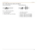
Page 36: ...odule USB 2 0 Status LEDs L R474 BXE 1 USB 2 0 status LED 2 Connect status LED 3 Link status LED 1 USB 2 0 status LED 2 Connect status LED 3 Link status LED The following tables show the respective LED states colors of the CPU add on module column 2 and the CON add on module column 3 for the respective situation Pos LED CPU Unit LED CON Unit Description of possible situations 1 Off Off USB 2 0 Lin...

Page 37: ...column 2 and the CON add on module column 3 for the respective situation Pos LED CPU Unit LED CON Unit Description of possible situations 1 Off Off USB 2 0 Link connection between CPU Unit and CON Unit not available 2 Off Off 3 Green flashing Green flashing 1 Off Off USB 2 0 Link connection between CPU Unit and CON Unit available USB connection between CPU Unit and source not available 2 Off Off 3...

Page 38: ...Pos 2 Description Off Green Link connection available Off Flashing green No link connection available Flashing green Green Link connection failure flashes for approx 20 s following each occurring connection failure Status LEDs for Link Connection Fiber Pos 1 Pos 2 Description Off Green Link connection available Off Flashing red No link connection available Flashing red Green Link connection failur...

Page 39: ...de fan cartridge module Status LEDs 1 Status LED Pos 1 Description Failure fan is not operable Green Fan runs with reduced speed until 40 C with parameter set see chapter 7 2 4 page 45 Light blue Operating condition The light blue LED is very bright and might also appear as white 1 ...

Page 40: ... modules offer the possibility to call up the command mode using a plugged in keyboard The command mode enables access to several functions of connected KVM devices using additional keyboard commands if necessary For more information about the command mode and keyboard commands please refer to the manual of the respective extender module Mini USB interface Some modules can be parametrized or updat...

Page 41: ...ith CPU Unit audio OUT 2 Connect the audio OUT on the CON Unit to headphones or suitable speakers 3 Connect the audio IN on the CON Unit to a suitable microphone 6 2 Connecting Add on Module Analog Audio Serial RS422 1 Connect the audio source to the CPU Unit e g computer audio OUT with CPU Unit audio IN computer audio IN with CPU Unit audio OUT 2 Connect the serial port of the source to the CPU U...

Page 42: ...hes In the delivery state all DIP switches are set to the bottom input The DIP switches belong to the pins listed below Pin 1 Pin2 Pin 3 Pin 4 Pin 5 Pin 6 Pin 7 Pin 8 Pin 9 DIP Switch 1 2 3 4 5 6 7 8 There are two options to use the GPIO add on module depending on the DIP switch positions output interface for LED connection for MSC Multi Screen Control 5 V 137 mA per channel input interface for pu...

Page 43: ...ll switches must be set to lower position to use the GPIO module as an input interface with an external switching solution with up to eight push buttons In the CON Device settings matrix configuration there are three options individually for each of the eight inputs Please refer to the Draco tera matrix user manual Macro call a macro Favorite switch current CON to a favorite CPU device in Full Acc...

Page 44: ... rate 44 1 kHz SRC48000 Activate sample rate conversion sample rate 48 kHz SRC88200 Activate sample rate conversion sample rate 88 2 kHz SRC96000 Activate sample rate conversion sample rate 96 kHz SRC176400 Activate sample rate conversion sample rate 176 4 kHz SRC192000 Activate sample rate conversion sample rate 192 kHz SRC_NONE Deactivate sample rate conversion SRCXXXXX X Set a delay enter the a...

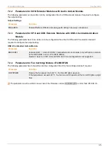
Page 45: ...f required to configure the output setting USB 2 0 embedded Add on Module Parameter Function ENAUSB11 Activate USB 1 1 mode for USB 2 0 embedded add on modules only with add on module L474 R474 BXE not for L474 R474 BXE2 Needs to be set on CPU Unit and CON Unit mixed configurations not supported 7 2 4 Parameters for Fan Cartridge Module 474 MODFAN The following parameter has to be written into the...

Page 46: ... module opens a flash drive containing the Config txt file 2 Open the Config txt file in a text editor 3 Ensure that CFG is written in the first line of the file 4 Add a line break directly behind CFG 5 Add the parameter s in capitals in the line below CFG one line per parameter 6 Add a line break directly behind each parameter 7 Delete everything that follows the entered parameter s including bla...

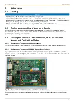
Page 47: ...ODY The safety instructions and conditions described in the chassis manual must be observed to avoid personal injury and damage to components 8 3 Updating the Firmware of Add on Modules USB 2 0 Stand alone Modules and Fan Cartridge Module 8 3 1 Updating the Firmware of Add on Modules The most add on modules can be updated via the Mini USB service port of extender modules by copy paste 8 3 2 Updati...

Page 48: ...DFAN pfw file onto the fan cartridge module without deleting the old one first copy and overwrite 3 Manually power off the fan cartridge module 4 Power on the fan cartridge module The fan cartridge module starts automatically with the new firmware 8 3 4 Updating the Firmware of Analog Add on Modules Analog audio add on modules cannot be field updated via Mini USB interface or matrix They need to b...
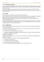
Page 49: ...the source available Check connection via serial cable No serial connection to the end device e g touch screen keyboard available Connect serial end device and switch it on Check connection via serial cable Touchscreen is not operational Hardware handshake Adjust serial interface to X ON X OFF software handshake 9 3 Add on Module Analog Audio Diagnosis Possible reason Measure CON Unit No signal at...

Page 50: ... Interface side add on module digital audio Failure indication Diagnosis Possible reason Measure CPU Unit LED 1 lights up red No audio connection to the audio source available Connect a digital audio source Check the connection of the audio cable between the CPU Unit and the audio source No signal available Switch the digital audio source on Activate the digital output at CPU audio source CON Unit...

Page 51: ...f the USB HID cable to the USB HID device Connect a USB HID device Contact your distributor if necessary The USB HID device is not supported Check the compatibility New connection of the USB HID device Contact your distributor if necessary No USB HID connection to the source available Check the connection of the USB cable to the source select another USB HID port if necessary Remove the USB and po...

Page 52: ...D USB 2 0 device without function No USB 2 0 device connected Check the cable to the USB 2 0 device Connect a USB 2 0 device Contact your distributor if necessary The USB 2 0 device is not supported Check the installation of the USB 2 0 device and the necessary drivers at the CPU New connection of the USB 2 0 device Contact your distributor if necessary USB 2 0 device without function CPU Unit and...

Page 53: ... select another USB port if necessary Remove the USB and power cables first connect the power cable then connect the USB cable and restart the CPU Unit LED 1 flashes Link connection failure between CON Unit and CPU Unit Check the interconnect cable Check the connectors LED 2 flashes No connection between CON Unit and CPU Unit available Check the interconnect cable Check the connectors CPU Unit LED...

Page 54: ... Fan Cartridge Module Fig 53 Interface side fan cartridge module Failure indication Diagnosis Possible reason Measure LED 1 lights up red Fan is not operable Check the firmware version The fan is defect Contact your distributor if necessary 1 ...

Page 55: ...arcode scanners or special keyboards However support cannot be guaranteed for every USB HID device In certain cases such devices can be operated with special firmware Extension If it is required to extend the USB HID signals on CPU or console side e g mounting requirement the signals can be extended either via a 3 0 m A B cable 247 U2 or a 3 0 m USB A A extension cable 436 USB20 The compatibility ...

Page 56: ...ach channel each LED is 5 V and provides a maximum of 137 mA 1 1 A in total for the whole GPIO add on module All 8 LEDs share the 5 V pin The 5 V connectors of the LEDs are connected to the respective ground pin of the GPIO add on module 10 1 6 RS232 Serial Extender modules with serial interface option support a full duplex transmission with a real hardware handshake up to a baud rate of 115 200 B...

Page 57: ...l Extender modules with a serial interface RS422 D Sub 9 support a differential full duplex transmission up to a baud rate of 115 200 Bd The CPU Unit is designed as controlling device and can for example be connected directly to video or media servers The CON Unit is designed as a controlled device and can be connected directly to remote controllers Parameter Value Connection Format Sony Standard ...

Page 58: ...to the audio input of the sound card blue Choose this connection if the microphone has its own pre amplifier The CON Unit can also provide pre amplification of a microphone To activate the pre amplification Open the CON Unit Locate the pins marked with MICJP on the audio board and close the pins with a jumper Specification Analog Audio Parameter Value Transmission format Digitized virtually CD qua...

Page 59: ...rter for the output by writing the parameter in a new line The following sample frequencies are available 32 0 kHz write SRC32000 in the Config txt file of the CPU Unit 44 1 kHz write SCR44100 in the Config txt 48 0 kHz writeSCR48000 in the Config txt file of the CPU Unit 96 0 kHz writeSCR96000 in the Config txt file of the CPU Unit You can set a delay for converting the sample rate The time is se...

Page 60: ...antom power can only be activated on the audio input side CPU module The microphone has to be connected to the audio input of the CPU module To activate phantom power the switch on the CPU module has to be pressed and clicked into the pressed position NOTICE Damage to audio output devices from phantom power If audio output devices e g loudspeakers are operated with phantom power unexpected damage ...

Page 61: ...in Config txt file Compatibility Extender modules with balanced audio interface are compatible to extender modules with digital audio interface regarding the transmission of the audio standard 2 channel PCM The compatibility shall be applied to the add on module digital audio and the extender modules of the 481 491 and 483 493 Serie The compatibility is regardless of the input or output side this ...

Page 62: ...he operation of the devices without mounted ferrites leads to a loss of conformity with the EU directives Mount ferrites on both sides of all Cat X cables near the device to maintain regulatory EMC compliance Type of Interconnect Cable The extender modules require interconnect cabling specified for Gigabit Ethernet 1000BASE T The use of solid core AWG24 shielded Cat 5e or better is recommended Typ...

Page 63: ...n house patch cable I AD ZN H 4G50 in house or outdoor breakout cable resistant Cable notations according to VDE Maximum Transmission Range for Video and USB HID Signals End to End Connection NOTICE Transmission ranges when using add on modules with transparent USB When using L474 R474 add on modules with transparent USB the binding specifications stated in the data sheets of the add on modules ap...

Page 64: ...d 5 GND Black 10 3 3 PS 2 Connector Pin Signal Pin Signal 1 DATA 4 CLK 2 GND 5 Not connected 3 5 V DC 6 Not connected 10 3 4 D Sub 9 Serial RS232 DCE CPU Modules Connector Pin Signal Pin Signal 1 Not connected 6 DTR out 2 TxD out 7 CTS in 3 RxD in 8 RTS out 4 DSR in 9 Not connected 5 GND 10 3 5 D Sub 9 Serial RS232 DTE CON Modules Connector Pin Signal Pin Signal 1 Not connected 6 DSR out 2 RxD in ...

Page 65: ...0 3 7 D Sub 9 Serial RS422 CON Modules Connector Pin Signal Pin Signal 1 GND 6 Tx GND 2 Tx A out 7 Tx B out 3 Rx B in 8 Rx A in 4 Rx GND 9 GND 5 Not connected 10 3 8 D Sub 9 GPIO Connector Pin Signal Color 1 1 Ground 2 1 Ground 3 5 V DC 4 2 Ground 5 2 Ground 6 3 Ground 7 3 Ground 8 4 Ground 9 4 Ground 10 3 9 3 5 6 35 mm Stereo Jack Plug Connector Pin Signal 1 GND 2 Audio IN OUT L 3 Audio IN OUT R ...

Page 66: ... 1 GND 4 IN 2 5 IN 2 6 IN 2 GND 10 3 11 Phoenix Terminal Block 6 pole CON Modules Connector Pin Signal 1 OUT 1 2 OUT 1 3 OUT 1 GND 4 OUT 2 5 OUT 2 6 OUT 2 GND 10 3 12 RCA Cinch Connector Pin Signal 1 GND 2 Data IN OUT 10 3 13 Mini XLR Connector Pin Signal 1 GND 2 Data 3 Data 10 3 14 Toslink Connector Diode Signal 1 Data IN OUT ...

Page 67: ...60 mA Interface CPU module CON module Maximum current draw Maximum power consumption Maximum current draw Maximum power consumption Analog audio RS232 70 mA 0 3 W 70 mA 0 3 W Analog audio RS422 70 mA 0 3 W 70 mA 0 3 W Digital audio 100 mA 0 5 W 100 mA 0 5 W Symmetrical audio 500 mA 2 3 W 370 mA 1 7 W USB 2 0 embedded up to 36 Mbit s 90 mA 0 4 W 170 mA 0 8 W USB 2 0 embedded up to 50 100 Mbit s 110...

Page 68: ... Stand alone Modules Product type Max weight L474 Max weight R474 BXUC 130 g 135 g BXUS 135 g 140 g 10 6 3 Fan Cartridge Module Product type Weight 474 MODFAN 60 g 10 7 Environmental Conditions and Emissions Parameter Value Operating temperature 5 to 45 C 41 to 113 F Storage temperature 25 to 60 C 13 to 140 F Relative humidity Max 80 non condensing Operating altitude Max 2 500 m 7 500 ft Heat diss...

Page 69: ...distributor if necessary Issue date of the existing manual Nature circumstances and duration of the problem Components included in the system such as graphic source CPU OS graphic card monitor USB HID USB 2 0 devices interconnect cable including manufacturer and model number Results from any testing you have done 11 2 Shipping Checklist 1 To return your device you need an RMA number Return Materia...

Page 70: ...bilities to a video source e g graphics card Fiber Single mode or multi mode fiber cables KVM Keyboard video and mouse LPCM LPCM Linear Pulse Code Modulation is a pulse modulation method also known as an uncompressed data format The LPCM method is used for converting analog audio into digital audio with evenly large value ranges Mini DisplayPort A VESA standardized interface for an all digital tra...

Page 71: ...gnals F05 plug connection USB HID USB HID devices Human Interface Device allow users to interact with computers There is no need for a special driver during installation When connecting the message New USB HID device found is reported Typical USB HID devices include keyboards mice graphics tablets and touch screens Storage video and audio devices are not USB HID devices ...

Page 72: ...Mini USB 55 PS 2 55 RS232 Serial 56 RS422 Serial 57 USB 2 0 transparent 56 USB HID 55 L LEDs Add on Modules Balanced Audio 34 Digital Audio 33 USB 2 0 embedded L R474 BXE 36 USB 2 0 embedded L R474 BXE2 37 USB HID 35 Fan Cartridge Module 39 USB 2 0 Stand alone 38 M Maintenance 47 Cleaning 47 Firmware Update 47 Add on Modules 47 Analog Add on Modules 48 Fan Cartridge Module 48 USB 2 0 Stand alone M...

Page 73: ... 28 Digital Audio unidirectional L R474 BDA 27 L R474 BDD 26 L R474 BDE 27 L R474 BDE2 27 L R474 BDH 28 L R474 BDX 26 GPIO R474 BGA 30 R474 BGE2 30 R474 BGX 30 USB 2 0 embedded L R474 BXE 22 L R474 BXE2 22 USB HID L R474 BXH 22 Fan Cartridge Module 32 USB 2 0 Stand alone Modules L R474 BXUC 31 L R474 BXUS 32 S Scope of Delivery 21 Status Indication 33 Add on Modules Balanced Audio 34 Digital Audio...

Page 74: ...arent 56 USB HID 55 MTBF 68 Power Consumption 67 Weight 68 Add on Modules 68 Fan Cartridge Module 68 USB 2 0 Stand alone Modules 68 Troubleshooting Add on Modules Analog Audio 49 Digital Audio 50 Serial Interface 49 USB 2 0 embedded 52 USB HID 51 Fan Cartridge Module 54 General Failures 49 USB 2 0 Stand alone Module 53 ...

Page 75: ...erface side L R474 BSE 25 Fig 19 Interface side L R474 BSE2 25 Fig 20 Interface side L R474 BSH 26 Fig 21 Interface side L R474 BDX 26 Fig 22 Interface side L R474 BDD 26 Fig 23 Interface side L R474 BDA 27 Fig 24 Interface side L R474 BDE 27 Fig 25 Interface side L R474 BDE2 27 Fig 26 Interface side L R474 BDH 28 Fig 27 Interface side L R474 BB2X 28 Fig 28 Interface side L R474 BB2E2 28 Fig 29 In...

Page 76: ...rface 43 Fig 47 Example Config txt with Parameter 46 Fig 48 Base module and USB 2 0 module of a USB 2 0 stand alone module 47 Fig 49 Interface side add on module digital audio Failure indication 50 Fig 50 Interface side add on module USB HID Failure indication 51 Fig 51 Interface side add on module USB 2 0 embedded Failure indication 52 Fig 52 Interface side USB 2 0 stand alone modules Failure ind...

Page 77: ...ge Log This table offers an overview about the most important changes available such as new functions changed configuration or operation Edition Date Chapter New functions changes REV01 00 2022 08 19 Initial user manual for 474 add on modules ...

Reviews: