474-Add-on Modules
Description
35
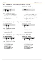
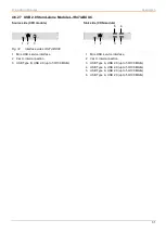
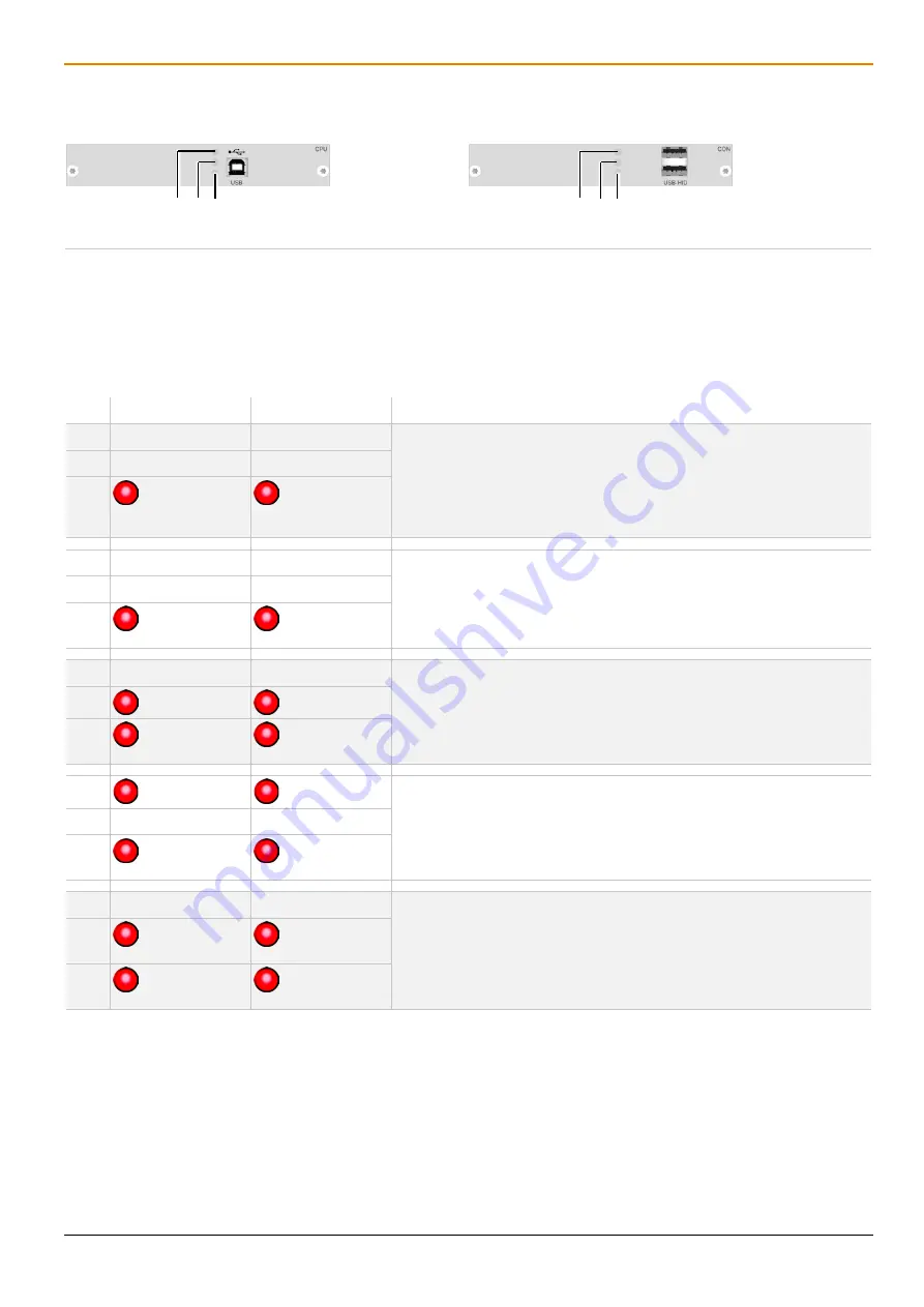
4.7.3 Add-on Module USB HID
Source side (CPU module)
Sink side (CON module)
Fig. 40
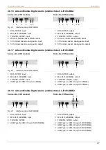
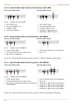
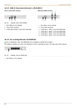
Interface side add-on module USB HID - Status LEDs
1 USB HID device 1 status LED
2 USB HID device 2 status LED
3 Link status LED
1 USB HID device 1 status LED
2 USB HID device 2 status LED
3 Link status LED
The following tables show the respective LED states/colors of the CPU add-on module (column 2) and the CON add-
on module (column 3) for the respective situation.
Pos. LED CPU Unit
LED CON Unit
Description
1
Off
Off
•
Link connection between add-on module and extender module
available.
•
No link connection between CPU Unit and source available.
•
No USB HID device connected or not supported USB device
connected.
2
Off
Off
3
Red, slowly
flashing
Red, slowly
flashing
1
Off
Off
•
Link connection between add-on module and extender module,
and between CPU Unit and source available.
•
No USB HID device or unsupported USB device connected.
2
Off
Off
3
Red, fast
flashing
Red, fast
flashing
1
Off
Off
•
Link connection between add-on module and extender module,
and between CPU Unit and source available.
•
Keyboard connected to USB HID port 1 or 2.
2
Red
Red
3
Red, fast
flashing
Red, fast
flashing
1
Red
Red
•
Link connection between add-on module and extender module,
and between CPU Unit and source available.
•
Mouse connected to USB HID port 1 or 2.
2
Off
Off
3
Red, fast
flashing
Red, fast
flashing
1
Off
Off
•
Link connection between add-on module and extender module,
and between CPU Unit and source available.
•
Keyboard connected to USB HID port 1 or 2.
•
Keyboard input active.
2
Red
Red, fast
flashing
3
Red, fast
flashing
Red, fast
flashing
3
2
1
3
2
1

