background image

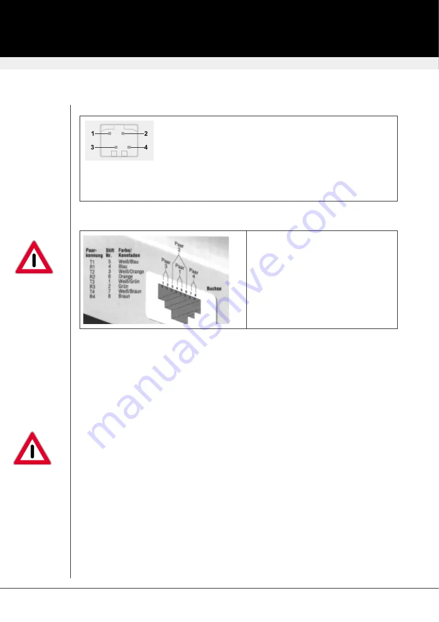
Power Supply Socket

1

GND

2

Erde

3

n.c.

4

+6VDC

GEHÄUSE

Schirm

At the plug terminal on the outside of both
interface boxes a direct current power
supply with 6V/DC has to be connected. We
recommend to use our suggested p.s.u.
because GND andEARTH shouln’t be
connected. Please mount near to the
devices ferrite rings in the DC line, to
protect against electromagnetic
interferences.

Interconnection Cable: Cat5

To connect Local and Remote Units, please
use S/UTP (Cat5) cable acc. to EIA/TIA
56A or TSB 36 or Digital STP 17-03170.
Four pairs AWG 24. Pinout acc. EIA/TIA
568A (10BaseT). Screen must be
connected on both ends. To enhance EMI
resistance, both end should carry a ferrite
near to the connectors. Please be careful to
have a tension free connection!.

Hints for using CATx-Cables

The Local and Remote Units are interconnected by industry standard structured cabling
(Category 5, Cat5e, Cat6, Cat7 UTP/STP, 4-pair) terminated with RJ45 connectors. This cable is
not supplied with the Extenders. The cable used should be solid trunk cable

.

Stranded patch

cable will result in dramatically reduced Interconnection distances (only 60% of trunk cable).

Note: That failure to wire the twisted pairs correctly will impair the video quality dramatically and /
or prevent correct operation.

Although a single continuous length of interconnect cable is preferable, operation is possible
through multiple patch panels. However, the more patch panels the cable is routed through, the
greater the chance of video signal degradation.

Interconnection Cable: Fibre

Use for interconnecting the local and remote unit:

Multimode Modules:

Two fibers 50μm or 62.5μm. E.g. I-V(ZN)H 2G50 (Inhouse patchcable) or

I-V(ZN)HH 2G62,5 (Inhouse Breakout cable) or I/AD(ZN)H 4G50 (inhouse OR outdoor Breakout
cable, stress resistant) or A/DQ(ZN)B2Y 4G62,5 (outdoor cable, stress resistant with protection
against animal biting) All notations acc. VDE specification.

revision: January, 2004

DAVX - dig. A/V-Extender

Connectors/Cables

23

4pol Hirose

Summary of Contents for K450-1S

Page 1: ...e parts DAVX Digital Audio Video Extender unidirectional transmission over Cat5 digital Audio RS232 K452 1S unidirectional transmission over Cat5 analog Audio RS232 K452 2S unidirectional transmission...

Page 2: ...efully Please record the serial number and the date of purchase inside of this manual The serial number is located on the backside of the units These data would be important if you ever need to repair...

Page 3: ...eatures 22 Connectors Cables 22 Transceiver Modules Fiber Transmission 24 Diagnostics 25 Getting Started 26 Firmware Upgrade 27 IR Control 27 Usage of IR Control 27 Serial Interface V24 RS232 28 analo...

Page 4: ...tance of 400m You need only a single fibre pair The RS232 Interface allows to remotely control your devices e g your camera The bidirectional devices allow simultaneous transmissions in both direction...

Page 5: ...g bidirectional near CD Quality 38 4kHz 16Bit serial RS232 fully transparent with Handshake up to 19200 Baud Interconnect Cable not in schedule of parts Cat5 5e 6 7 100m Installation cable 4x2xAWG24 o...

Page 6: ...r of these signals are used for hardware handshaking in addition to TX RX However because each handshaking line can support signals up to 19 200 Baud it is possible to configure the serial interface t...

Page 7: ...UTP STP 4 pair terminated with RJ45 connectors This cable is not supplied with the Extenders The cable used should be solid trunk cable Stranded patch cable will result in dramatically reduced Interco...

Page 8: ...hazards All adjustments have been made at the factory prior to shipment of the device No maintenance or alteration to the device is required Tampering with or modifying the performance of the device...

Page 9: ...12 4 Launched Power Average into multimode fiber 50 m or 62 5 m diameter or into singlemode fiber 9 m diameter 5 dBm 9 5 dBm min 3 dBm 11 dBm min average Wavelength 850 nm 1300 nm Sensitivity Average...

Page 10: ...mind that all setup processes have to be done at the remote unit Exception Cat5 devices with digital audio must be setup for Video Source and Video Format at the local unit Connecting Up Switch off yo...

Page 11: ...layed below to setup your extender system Usage of IR Control The system is modified by an Infrared remote control IRC type RC univers 15 With this remote control up to 4 different devices can be cont...

Page 12: ...ff toggle 1 Input Select Toggles between FBAS and Y C SVGA Input factory default FBAS 2 Video Mode Toggles between PAL and NTSC Format factory default PAL 9 Factory Reset Reset the DAVX System to fact...

Page 13: ...plification to 17dB Connect up the extender as follows Take the line level output from your sound card green connector and connect to Line In on the extender A set of powered speakers may be connected...

Page 14: ...ectional with digital Audio order notation DAVX MM DIG2 parts no K450 1D DAVX Multimode A V Extender bidirectional with analogue Audio order notation DAVX MM ANA2 parts no 450 2D DAVX Singlemode A V E...

Page 15: ...and remote interface is not included Caution Only use the power supply originally supplied with this product If you are not able to use the p s u s originally supplied please contact your dealer for...

Page 16: ...e harmful interference in which case the user will be required to correct the interference at his own expense Disclaimer While every precaution has been taken in the preparation of this manual the man...

Reviews: