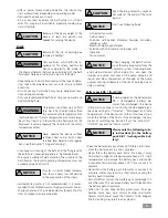
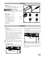
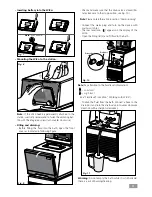
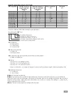
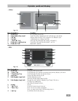
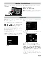
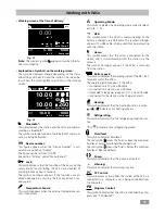
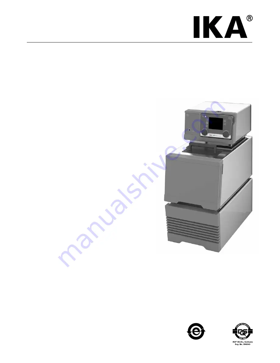
IKA CBC 5 control, Operating Instructions Manual
The IKA CBC 5 control Operating Instructions Manual is a comprehensive manual designed for easy use and download. Access this essential resource free of charge on 88.208.23.73:8080 to unlock step-by-step guidance and maximize your product's potential. Get your hands on this indispensable manual today!
Share
Download


Reviews:
No comments
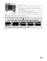
Related manuals for CBC 5 control

FENA-01
Brand: ABB Pages: 2

FEPL-02 Ethernet POWERLINK
Brand: ABB Pages: 2

FSCA-01
Brand: ABB Pages: 52

ACH550 series
Brand: ABB Pages: 6

Relion 615 series
Brand: ABB Pages: 136

Relion 670 series
Brand: ABB Pages: 760

COM600 series
Brand: ABB Pages: 56

ACS850-04 series
Brand: ABB Pages: 296

650 series
Brand: ABB Pages: 320

EAN823
Brand: ABB Pages: 17

COM600 series
Brand: ABB Pages: 104

REC650 ANSI
Brand: ABB Pages: 370

FDNA-01
Brand: ABB Pages: 2

FPBA-01 PROFIBUS DP
Brand: ABB Pages: 2

615 Series ANSI
Brand: ABB Pages: 60

5800 Series
Brand: S&C Pages: 40

7 Series
Brand: Watts Pages: 2

6000 Series
Brand: Mako Networks Pages: 15


