
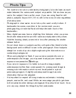

If you are shooting with the camera’s built-in flash and the camera lens
is set to the widest angle setting, you may need to zoom the lens slightly
or a dark area may appear in a lower corner of close-up photographs.
The lens port may block some of the light. Install the Diffuser,
page 14
,
and zoom in to eliminate any dark areas noted in your photographs
(You
can test this above water)
.
For the best results, we recommend using external Strobes.
The camera’s built-in flash CANNOT be used with optional Wide Angle or
Accessory lenses.
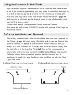
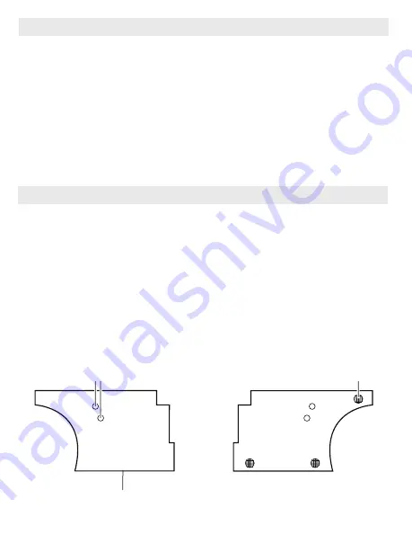
Using the Camera’s Built-in Flash
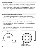
Deflector Installation and Removal
The factory installed flash Deflector should be removed and replaced by
the Diffuser,
page 14
, when using ONLY the built-in camera flash and no
external strobes. To
remove
, lift the bottom of the Deflector with your
thumb, or a Pen or Pencil tip to loosen and pull the Deflector away from
the inside front of the housing. To
install
, line up the corresponding
Velcro dots on the housing front with the
Deflector Back
and press the
Deflector into its factory installed position next to the lens port. If
positioned properly, the small deflector holes will line up with the Fiber
Optic Port holes.
Deflector Front
(view from inside housing)
Bottom of Deflector
Deflector Holes
Deflector Back
(view from outside housing)
13
Velcro


