background image


14

Warnings concerning operation


-


Always handle the tool with care. Never play with the tool. 

-


Always stand in balance. Do not use the tool on scaffoldings, ladders or on other unstable sur-
faces. 

-


Never pull the trigger unless the nose is directed toward the work. 

-


Keep others at a safe distance from the tool while it is in operation. 

-


Never let children touch the tool. Only adults with experience or training to operating the tool 
are allowed to use it. 

-


The operator must not hold the trigger pulled on contact trip tools except during fastening op-
eration as serious injury could result if the trip accidentally contacted someone or something, 
causing the tool to cycle. 

-


Keep your hands and body away from the discharge area of the tool. A contact trip tool may 
bounce from the recoil of driving a fastener and an unwanted second fastener may be driven. 

-


Check operation of the contact trip mechanism frequently. Do not use the tool if the trip is not 
working correctly as accidental driving of a fastener may result. Do not interfere with the proper 
operation of the contact trip mechanism. 

-


Do not drive nails on top of other nails or with the tool at an overly steep angle as this may 
cause deflection of nails. 

-


Do not drive nails close to the edge of the workpiece as the wood may split, allowing the nail to 
be deflected and cause injury. 


Follow all instructions and always note the warnings when using the tool. Use extra caution 
when trying to solve tool problems. 


OPERATION 


Air supply


1.


Use only clean, dry and regulated compressed air at 5,5-7,5bar (80-110psi). Never use oxygen, 
combustible gases or any other bottled gases as a power source for the tool as it may explode. 

2.


Never exceed maximum or minimum pressure. Too low or too high pressure would cause noise, 
fast-worn or misfiring. Refer to chapter ”Technical data” for setting the correct operating pres-
sure for the tool.  

3.


When connecting air supply always keep hands and body from discharge area of tool. 

4.


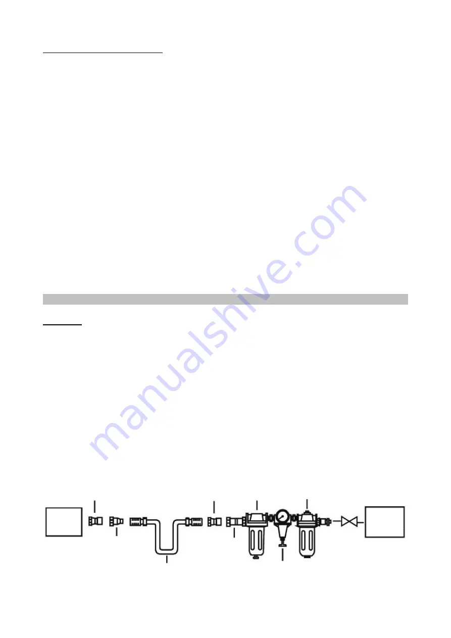
A filter-regulator-oiler system is required and should be located as close to tool as possible. (See 
fig. 1) 

5.


Keep air filter clean. A dirty filter will reduce the air pressure to the tool causing a reduction in 
power and efficiency. 

6.


For better performance, install a quick connector in your tool and quick coupler on the hose if 
possible. 

7.


Be sure all connections in air supply system are sealed to prevent air loss. 


Fig. 1


Tool 


 Comp- 

 ressor 


Lubricator 


 Quick 

coupler 

 Quick 

coupler 


 Cut-off 

  valve 

Air hose 

  Regulator 


Filter 

Quick 

connector 

Quick 

connector 

Summary of Contents for AWD45

Page 1: ...and Tel 358 20 1323 232 Fax 358 20 1323 388 www ikh fi HUOMIO Lue k ytt ohjeet huolellisesti ennen laitteen k ytt ja noudata kaikkia annettuja ohjeita S ilyt ohjeet my hemp tarvetta varten OBS L s nog...

Page 2: ......

Page 3: ......

Page 4: ...reunaa sill puu saattaa haljeta ja naula kimmota ja aiheuttaa loukkaantumisen Noudata kaikkia ohjeita ja huomioi varoitukset aina laitetta k ytt ess si Noudata erityist varovaisuutta ongelmatilanteit...

Page 5: ...k rki painetaan ty kappaleen pintaa vasten ja vedet n liipaisimesta Toisessa naulaustavassa sarjalaukaus liipaisin painetaan ensin pohjaan jonka j lkeen naulaimen k rki painetaan ty kappaleen pintaa...

Page 6: ...te tai o rengas 1 Vaihda o rengas 2 Vaihda 3 Vaihda kara tiiviste tai o rengas Ilmavuoto ty kalun alaosas sa 1 L ystyneet ruuvit 2 Vaurioituneet tai kuluneet o renkaat tai iskunvaimennin 1 Kirist ruuv...

Page 7: ......

Page 8: ......

Page 9: ...kjut inte f stelement n ra arbetsstyckets kanter d tr et kan splittras varvid f stelementet kan rikoschettera F lj samtliga anvisningar och uppm rksamma varningarna vid anv ndandet av verktyget Var ex...

Page 10: ...skenan mot underlaget och tryck in avtryckaren avfyring i f ljd Tryck in av tryckaren och tryck d refter skyddsskenan mot arbetsstycket f r kontinuerlig avfyring st tavfy ring Avfyringss ttet v ljs ge...

Page 11: ...la t tning eller O ring r skadade 1 Byt O ring 2 Byt 3 Byt utl sningsventilens k gla t tning eller O ring Luftl ckage n ra verktygets undre del 1 L sa skruvar 2 Slitna eller skadade O ringar eller st...

Page 12: ......

Page 13: ......

Page 14: ...y steep angle as this may cause deflection of nails Do not drive nails close to the edge of the workpiece as the wood may split allowing the nail to be deflected and cause injury Follow all instructio...

Page 15: ...face and pull the trigger sequential fire Pull the trigger and then depress the safety guide body against the work surface for continuous operation bump fire To select the firing mode press down the f...

Page 16: ...3 Trigger valve stem seal or o ring is damaged 1 Replace o ring 2 Replace 3 Replace trigger valve stem seal or o ring Air leak near bot tom of tool 1 Loose screws 2 Worn or damaged o rings or bumper...

Page 17: ......

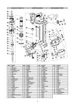
Page 18: ...agarm 76 Fj der 25 Verktygsk pa 51 Justeringsskruv 77 Blockdel 26 St td mpare 52 Justeringsskruv 78 Fj der NO DESCRIPTION NO DESCRIPTION NO DESCRIPTION NO DESCRIPTION 1 Bolt 27 O ring 53 Snap retainer...

Page 19: ...t mmelserna i maskindirektivet 2006 42 EG samt standarden EN 792 13 2000 A1 2008 Om produktens tekniska eller andra egenskaper f r ndras utan tillverkarens medgivande g ller denna verensst mmelse inte...

Reviews: