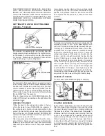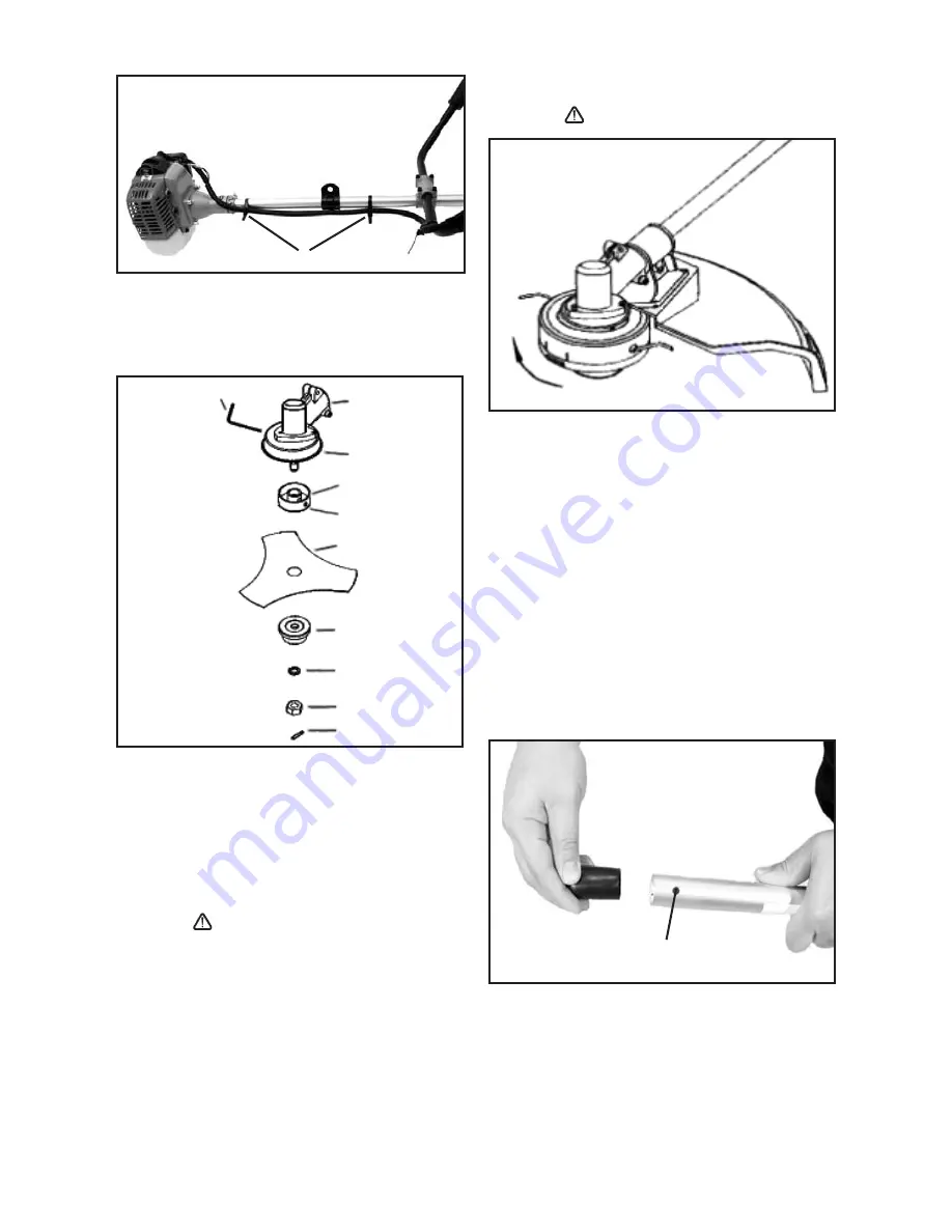
X
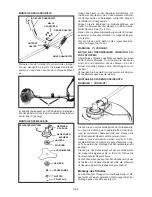
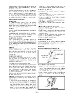
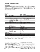
The accessories package includes 2 cable ties. Attach
the cable to the shaft using the two cable ties as shown
in the figure (X).
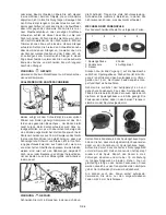
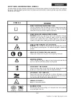
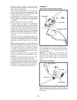
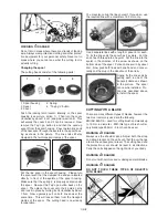
INSTALLING THE BLADE
SPLIT PIN 2x16
ALLEN KEY
GEAR BOX
SAFETY GUARD
BRACKET A
BORE
3-TOOTH BLADE
BRACKET B
TOOTHED WASHER
NUT
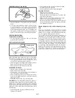
Install blade in the following order: Install holder A, the
3-tooth blade, holder B, the toothed washer, then fix all
with the nut with left-handed thread.
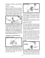
Align the bores in the gear case and holder A and in-
sert an Allen key (S=4mm).
Tighten the blade fastening nut with a matching box
wrench by turning it anti-clockwise.
Install the 2x16 split pin and bend out the ends.
WARNING
ATTENTION
STOP THE ENGINE IMMEDIATELY IF EXCESSIVE
VIBRATION OCCURS !
Excessive vibration of the blade indicates that it is not
properly installed. Stop the engine immediately and
check the blade. An improperly installed blade may
cause injury.
Operate the unit with original cutting tools of the manu-
facturer only.
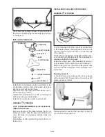
INSTALLING NYLON LINE CUTTING HEAD
WARNING
ATTENTION
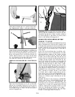
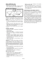
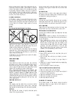
Turn the threaded bolt of the drive shaft until the bore
in the adapter plate is exactly aligned with the bore in
the main tube and put in the Allen in to lock the parts
in this position.
Retainer A must be applied. Retainer B, toothed wash-
er, nut and split pin should be kept. These parts are not
required to install the cutting head.
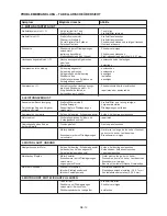
Screw the cutting head on the threaded bolt (turning it
anti-clockwise) until it is tight. Remove the Allen key.
When cutting with the nylon line cutting head, take
care that the black extension of the protection cover
is mounted.
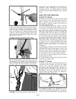
Mounting the shaft
To facilitate transport and storage this tool is equipped
with a two-part shaft. To assemble and mount the shaft
please proceed as follows:
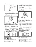
B
Remove protection cap from the lower shaft. Loosen fly
nut A, but do not fully unscrew.
GB-5


