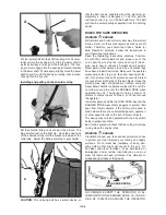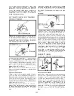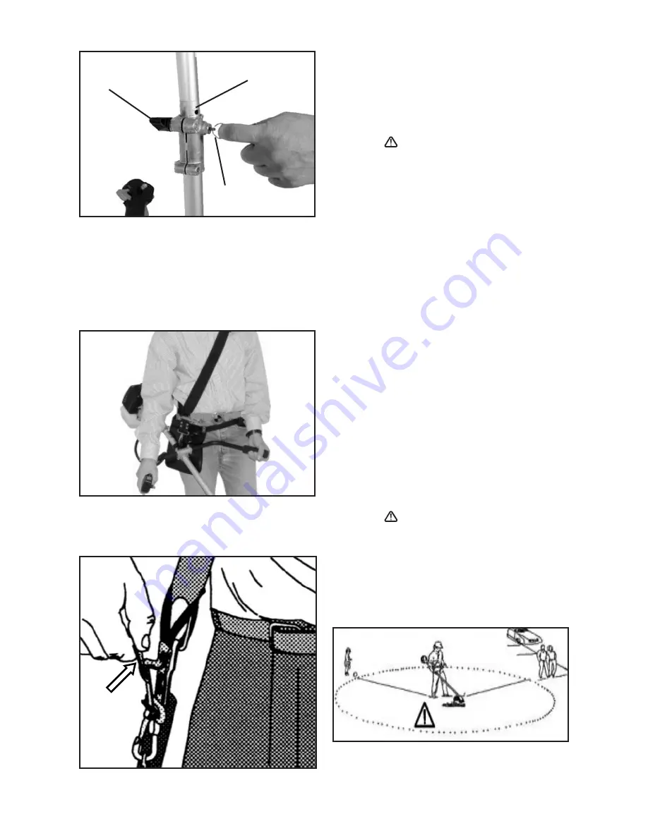
that the belt can be separated from the machine im-
mediately in case of emergency. To do this, pull the
red tension clip (Fig. x) of the belt with force. The belt
will then be automatically separated from the holding
device.
RULES FOR SAFE
OPERATION
WARNING
DANGER
All trimmers and brush cutter models may throw small
stones, metal or other small objects as well as cut-off
matter. Therefore you should read these ‘Rules for
Safe Operation’ carefully. Follow the instructions in
your Operating Instructions.
Read the Operating Instructions carefully. Familiar-
ize with the control elements and proper use of the
unit. Learn how to stop the unit and shut off the en-
gine. Learn how to unhook a harnessed unit quickly.
Never permit other persons to use the unit unless they
have been properly instructed. Make sure the operator
wears proper foot, leg, eye, face and hearing protec-
tion. Do not rely on the unit’s protection cover to protect
your eyes from ricocheting or thrown objects. Keep the
working area clear of bystanders, children and pets.
Never allow children to operate or play with the unit. Do
not allow anyone to enter the DANGER ZONE when
operating the unit. The danger zone is an area of 15
meters in radius (about 16 steps) or 50 feet around
the operator.
Insist that persons within the RISK ZONE beyond the
DANGER ZONE wear safety goggles to protect their
eyes from thrown objects. If the unit must be used in
areas where there are unprotected people, operate it
at a low speed to reduce the risk of thrown objects.
The device may only be operated with the stop switch
being in proper condition.
As a routine procedure check that the cutting tool stops
turning when the engine idles.
WARNING
DANGER
In addition to head, eye, face and ear protectors, shoes
to protect your feet improve your footing on slippery
surfaces. Do not wear ties, jewellery, or loose, dan-
gling clothing that might get caught in the unit. Do
not wear open-toed footwear, or go barefooted or
barelegged. Under certain circumstances, you must
wear full face and head protection. Pay attention to
kickback and strokes of the device.
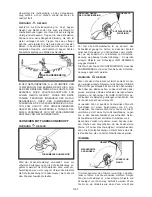
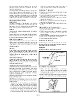
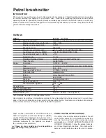
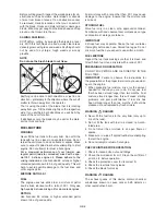
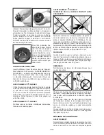
15 METERS
50 FEET
DANGER ZONE
NO PERSON EXCEPT THE OPERATOR IS AL-
LOWED WITHIN THE DANGER ZONE, I.E., IN A RA-
DIUS OF 15 METERS AROUND THE OPERATOR.
GB-6
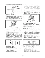
A
C
D
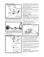
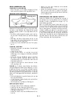
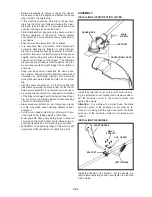
Put the lower shaft into the shaft coupling C and concur-
rently pull out the locking pin D. Slide the lower shaft in
as far as it will go and let go of the locking pin. The lock-
ing pin must engage into the opening B located laterally
in the lower shaft. Of necessary, slightly move the lower
shaft to-and-fro until the locking pin safely locks in place.
Then tighten the fly nut A.
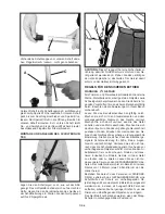
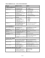
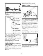
Installing and putting on the shoulder strap
Put the shoulder strap on as shown in the picture. The
hip pad shall rest on the right hip. Hook the snap hook
of the shoulder strap into the bracket provided at the
main tube. Adjust the strap according to your height.
x
CAUTION:
This carrying belt has a safety device so

