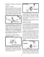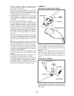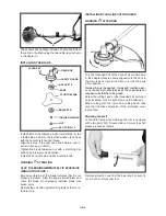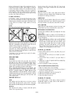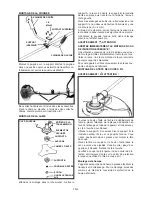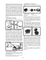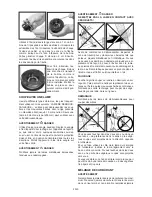
You may also coil up the line yourself. If you do so, use
the required line with a diameter of 2.5 mm only.
Use 2 separate lines with a length of about 2.1m each.
To fix the line ends the spool has 2 eyelets. Put the
end of each thread into an eyelet. Put the line into the
eyelet in the direction of the arrow as shown on the
bottom side of the spool. Put each line end in by about
2cm. Now grab both lines with one hand and concur-
rently coil them up in the direction of the arrow.
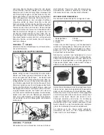
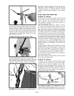
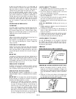
Finally, fix the line ends by
putting each in one of the
transport clamps as shown
in the picture. The spool
can now be installed. Pro-
ceed as described above
to install the spool.
CUTTING WITH A BLADE
There are many different types of blades, however the
two most commonly used are the following.
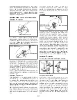
BRUSH BLADE – used for cutting brush and weeds up
to 15 mm in diameter. With this type of brush cutter,
only blade type 255mm / 3-tooth can be used.
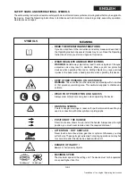
WARNING
DANGER
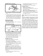
Always use the shoulder strap. Adjust both the strap
and strap bracket on the unit such that the unit hangs
a few inches above ground level. The cutting head and
the protection cover should be level in all directions.
Carry the unit strapped on the right side of your body.
WARNING
DANGER
Do not cut with dull, cracked or damaged metal blades.
WARNING
DANGER
DO NOT TOUCH THESE TYPES OF OBJECTS
WITH BLADE
WARNING
DANGER
Do not trim in areas where there are strands of fencing
wire. Always wear protective clothing and other protec-
tion equipment for your personal safety. Never cut in
areas where you cannot see what the cutting tool is
actually cutting.
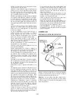
Changing the spool
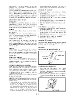
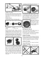
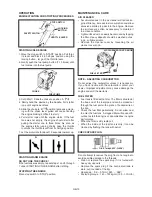
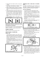
The cutting head consists of the following parts:
2
3
4
5
1
1 Spool housing 2 Spring
3 Spool 4 “Tap’n go” button
5 Cover
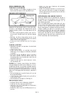
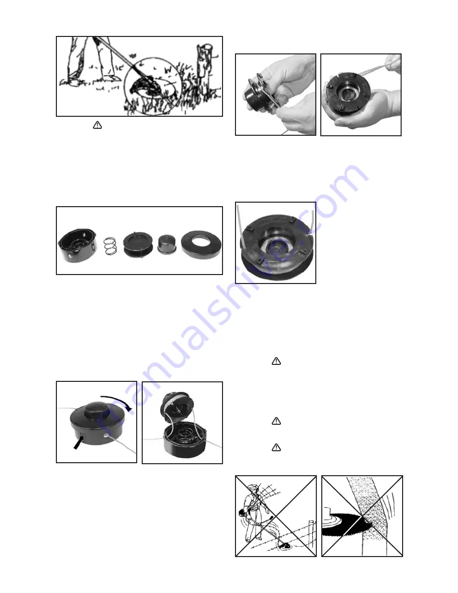
Push the locking latch located laterally on the spool
housing (see picture, action 1). Then turn the cover
clockwise by about 1.5 cm (see picture, action 2). This
will unlock the cover 5 and it can be removed. Now
remove the Tap’n go button 4 and then the used-up
spool 3 from
the spool housing. Pass the two line ends
of the new spool through the eyelets in the spool hous-
ing as shown in the picture. The line ends still stay
clamped in the two transport clamps pf the spool.
1
2
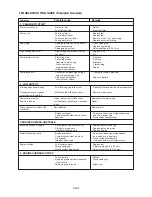
Put the line spool in the spool housing. Please turn
the spool such that the clamped line ends are located
directly in front of the eyelets of the spool housing.
Make sure that the spring 2 is properly seated under
the spool. Now put the Tap’n go button back on the
spool. Then place the cover onto the 4 guiding pins
and lock it in place by turning it anti-clockwise by about
1.5cm. Now vigorously pull on both line ends at the
same time. This will loosen them from the transport
clamps of the spool. The cutting head is now ready
for operation.
GB-
8

